Air coaxial output structure of an active antenna

A coaxial output, active antenna technology, applied in the fields of positioning, navigation and control, and aerospace systems, can solve the problems of product electrical performance impact, life cycle limitation, structural height limitation, etc., to achieve convenient installation, prevent self-excitation, The effect of increasing circuit isolation

Active Publication Date: 2019-05-24
BEIJING RES INST OF TELEMETRY +2
View PDF6 Cites 0 Cited by
  • Summary
  • Abstract
  • Description
  • Claims
  • Application Information

AI Technical Summary

Problems solved by technology

[0003] The existing output connection structure is mainly divided into three forms: the first is the use of dielectric wall connectors, this form is mostly used in the design of independent modular products, leaving a large margin for the overall size of the product, and the system interconnection space Sufficient situation; the second is the form of welding and interconnection between the cable and the connector. One end of the cable is welded to the output feed point of the RF printed board, and the other end is connected to the connector interface at a fixed position. The operation is more difficult and there are unreliable connections. Hidden dangers will affect the electrical performance of the product; the third type is the combination of pin type, hole type socket and cable. The output position of this type is more flexible, but it is easily affected by its own size and the turning radius of the cable, and the structural height is limited. And for special use environment requirements, such as airtight, watertight, etc., it is necessary to design the external structure to meet the environmental design requirements
At the same time, the cable is easily damaged due to external force bending during the debugging process, and the service life is limited
In summary, the above three forms all have certain limitations.

Method used


Image

  • Air coaxial output structure of an active antenna
  • Air coaxial output structure of an active antenna
  • Air coaxial output structure of an active antenna

Examples


Embodiment Construction

[0020] The present invention will be further described in detail below in conjunction with the drawings and specific embodiments:

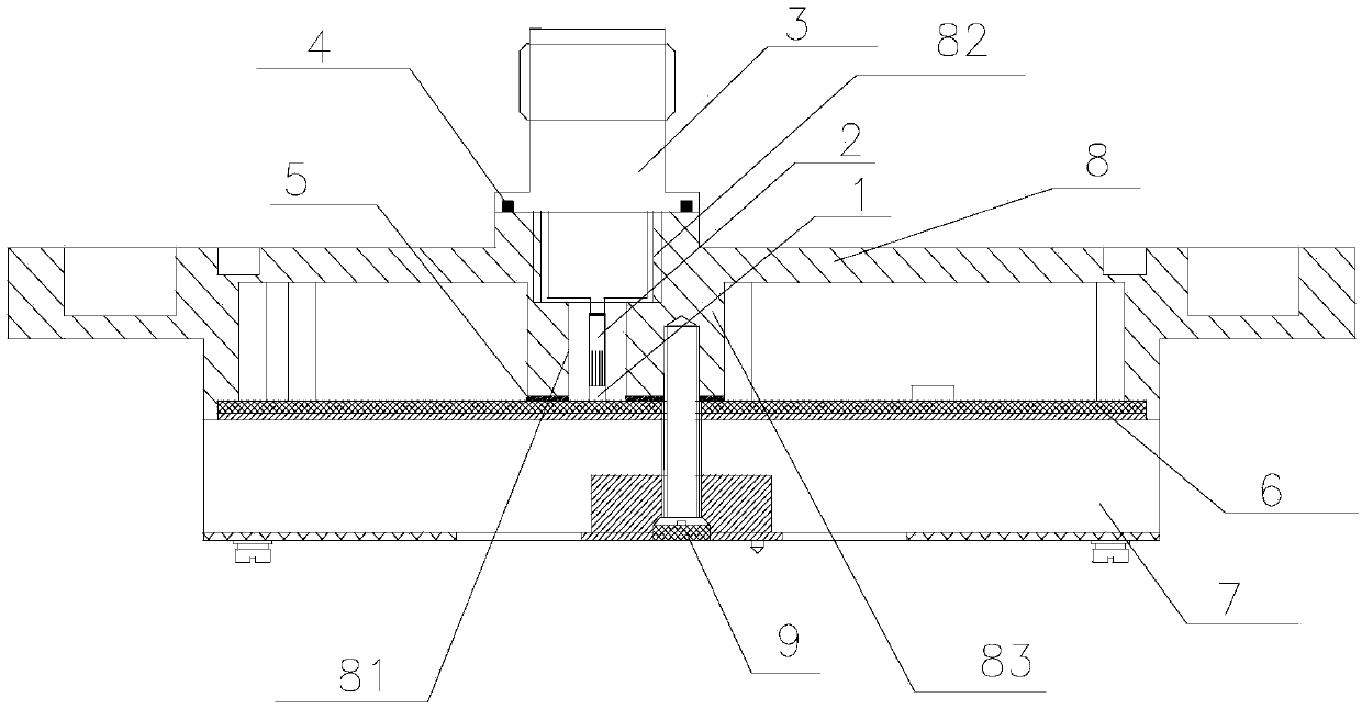
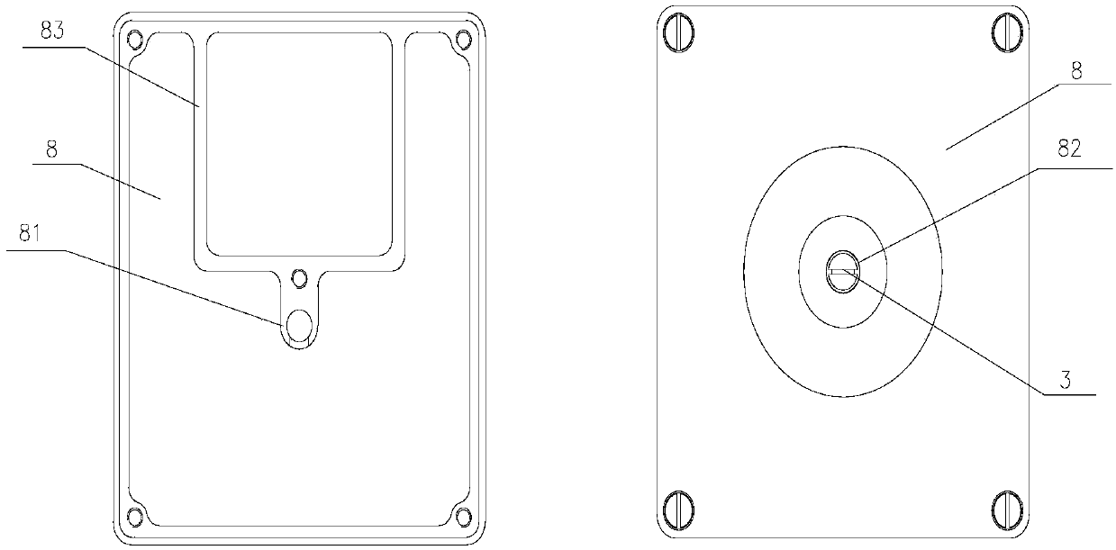
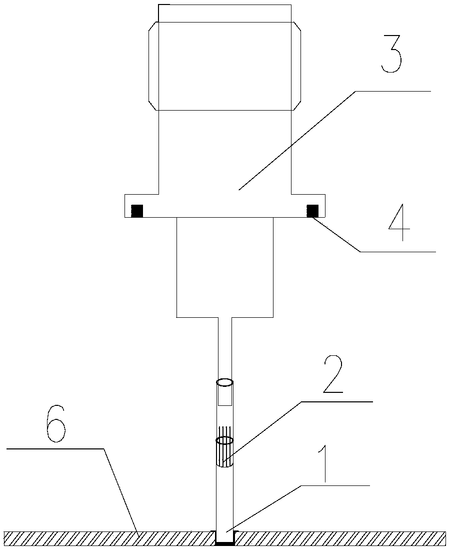
[0021] Such as figure 1 Shown is a cross-sectional structure diagram of the air coaxial output structure. From the figure, it can be seen that an air coaxial output structure of an active antenna includes a semi-closed hole sleeve 1, an elastic embedded locking structure 2, a pin connector 3 , Sealing rubber ring 4, adjusting gasket 5, radio frequency circuit board 6, shielding box body bottom plate 7, shielding box body cover plate 8 and fastening screws 9; among them, the shielding box body bottom plate 7 is located at the bottom of the RF air coaxial output structure The radio frequency circuit board 6 is fixedly installed on the upper surface of the bottom plate 7 of the shielding box; the adjusting pad 5 is fixedly installed on the upper surface of the radio frequency circuit board 6; the shielding box cover 8 is fixedly installed on the upper su...


PUM


Abstract

The invention, which relates to the fields of the aerospace system, positioning navigation, and control, provides an air coaxial output structure for an active antenna. The air coaxial output structure comprises a semi-closed hole type sleeve, an elastic embedded locking structure, a pin type connector, a sealing rubber ring, an adjusting gasket, a radio-frequency circuit board, a shielding box body base plate, and a shielding box body cover plate. The radio-frequency circuit board is fixedly installed on the upper surface of the shielding box body base plate; the adjusting gasket is fixedly installed at the upper surface of the radio-frequency circuit board; the shielding box body cover plate is fixedly installed at the upper surface of the shielding box body base plate; and the edge of the shielding box body cover plate is in contact with the upper surface of the radio-frequency circuit board. The elastic embedded locking structure is installed in the semi-closed hole type sleeve fixedly, vertically and axially. The pin type connector is fixedly installed at the upper surface of the shielding box body cover plate. The air coaxial output structure provided by the invention has advantages of optimizing the structural dimension, being convenient to install, being connected reliably, and arranging an output port flexibly and can met various installation needs.

Description

Technical field [0001] The invention relates to an aerospace system, positioning navigation and control field, in particular to an air coaxial output structure of an active antenna. Background technique [0002] In many fields such as positioning navigation and control systems, there are strict restrictions on the working environment of the internal components of the system, the overall structure size, the position of the output port, and the form of the output interface. In product design, it is necessary to not only meet the external indicators of the whole machine, but also take into account the electrical performance of the internal core modules, which puts forward higher requirements for the reliability design of the output structure. [0003] The existing output connection structure is mainly divided into three forms: the first is the use of media through-wall connectors. This form is mostly used in the design of independent modular products, leaving a large margin for the ov...

Claims


Application Information

Patent Timeline
Patent Type & Authority Patents(China)
IPC IPC(8): H01R13/40H01R13/6581H01Q1/50
CPCH01Q1/50H01R13/40H01R13/6581H01R2201/02
Inventor 赵丽丽李保平刘德喜
Owner BEIJING RES INST OF TELEMETRY
Why Eureka
Try Eureka