Battery wireless charging system for secondary side composite type compensation network

A secondary-side compensation and compensation network technology, applied in battery circuit devices, control/regulation systems, current collectors, etc., can solve the problems of increasing device stress, different compensation frequencies and parameters, and reducing transmission efficiency, reducing the transmission efficiency. Small device stress, avoid reactive power circulation, avoid the effect of complex communication

Active Publication Date: 2017-03-22
SOUTHEAST UNIV
View PDF5 Cites 31 Cited by
  • Summary
  • Abstract
  • Description
  • Claims
  • Application Information

AI Technical Summary

Problems solved by technology

In order to reduce the number of compensation devices and switching switches, networks with the same compensation parameters and resonant frequency can be optimally combined. Therefore, only the SS/PS and PP/SP composite structures of the four basic compensation networks have the same Resonant frequency and compensation parameters do not require additional resonant devices, and can realize constant current or constant voltage output and reactive power full compensation at the same time, but the mode switch is on the primary power supply side, so the control of the mode switch needs to be controlled through the transmitter and receiver Signal transmission between the communication system, the control is relatively complex, and the reliability is low
In the other two composite structures SS/SP and PP/PS, the mode switch is on the secondary side, which avoids the complicat

Method used


Image

  • Battery wireless charging system for secondary side composite type compensation network
  • Battery wireless charging system for secondary side composite type compensation network
  • Battery wireless charging system for secondary side composite type compensation network

Examples


Embodiment Construction

[0030] The specific implementation steps will be described below in conjunction with the description of the drawings and the technical solution.

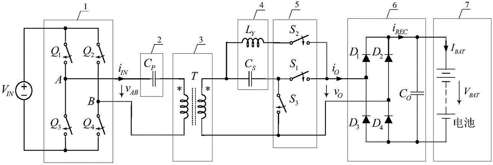
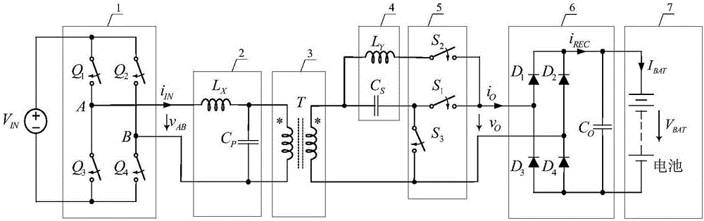
[0031] The battery wireless charging system of the secondary compound compensation network disclosed by the present invention specifically includes figure 1 The SS / S-LCL composite structure shown and figure 2 The LCL-LCL / LCL-S composite structure shown includes: high-frequency full-bridge inverter circuit 1, primary side compensation network 2 ( figure 1 The middle is the primary side compensation capacitor C P , figure 2 The middle is the primary side compensation capacitor C P and primary side additional inductance L X ), loose coupling transformer 3, secondary side compensation network 4 (secondary side compensation capacitor C S and secondary side additional inductance L Y ), constant current-constant voltage switching network 5, full-bridge rectification filter circuit 6, load battery 7. The constant current-constant...


PUM


Abstract

The invention relates to a battery wireless charging system for a secondary side composite type compensation network, for providing constant current and constant voltage output required by a battery charging process in sequence. Two kinds of novel composite topological structures, including SS/S-LCL and LCL-LCL/LCL-S are provided; and each novel composite topological structure comprises a high-frequency full-bridge inversion circuit, a primary side compensation network, a loosen coupling transformer, a secondary side compensation network, a constant current-constant voltage switching voltage, and a full-bridge rectifying and filtering circuit separately. Based on the intrinsic characteristic of a circuit, a constant current or a constant voltage irrelevant to a load is realized at specific frequency; conversion of two kinds of modes is realized through the constant current-constant voltage switching network; in addition, approximate zero reactive ring current of the circuit and soft switching of a switching device are realized concurrently, so that the efficiency is improved while the device stress is reduced; and the constant current-constant voltage switching network is placed on the secondary side, so that complex communication between a transmitting end and a receiving end of the wireless charging system is avoided, the control is simplified, and the reliability is improved.

Description

technical field [0001] The invention discloses a battery wireless charging system of a secondary-side composite compensation network, relates to battery wireless charging technology, and is suitable for battery wireless charging occasions such as electric vehicles and medical equipment. Background technique [0002] Wireless charging technology is an emerging technology that uses electromagnetic fields as the medium to transmit electric energy through electromagnetic theory. Since there is no electrical and mechanical connection between the power supply end and the power receiving end, it is easy to use, safe and reliable, so wireless charging technology has great application prospects. [0003] Battery charging usually includes two stages of constant current charging and constant voltage charging, so the wireless charging system needs to provide the battery with the required constant current and constant voltage output. The loosely coupled transformer used in the wireless ...

Claims


Application Information

Patent Timeline
IPC IPC(8): H02J7/00H02M3/335
CPCH02J7/025H02M3/33523
Inventor 曲小慧储海军
Owner SOUTHEAST UNIV
Why Eureka
Try Eureka