
Matrix control method for multiple battery packs in communication base station

A communication base station, matrix control technology, applied in the field of corresponding control units, can solve the problem of no battery charge and discharge management system, achieve good economic and social benefits, reduce carbon emissions and environmental pollution.

Pending Publication Date: 2017-03-22
刘杰
View PDF4 Cites 2 Cited by
  • Summary
  • Abstract
  • Description
  • Claims
  • Application Information

AI Technical Summary

Problems solved by technology

[0003] The DC power system of the communication base station power system usually uses lead-acid batteries as the backup power supply, that is, the charge and discharge management of the lead-acid battery is completed by the switching power supply monitoring system, and there is no independent battery charge and discharge management system

Method used


Image

  • Matrix control method for multiple battery packs in communication base station
  • Matrix control method for multiple battery packs in communication base station
  • Matrix control method for multiple battery packs in communication base station

Examples


Embodiment 1

[0051] Embodiment 1 (one group of lead-acid, two groups of ladder batteries, three or four types of mains):

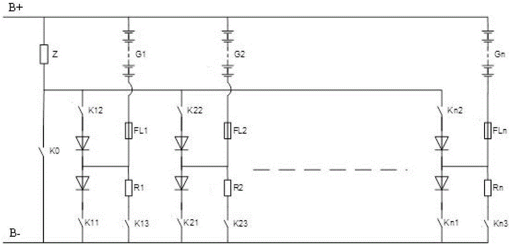
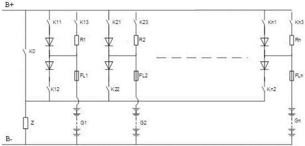
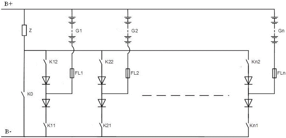
[0052] There are the first, second, and third combination circuit units, one of which uses lead-acid as the battery pack, and the other two uses step-by-step lithium batteries. Image 6 In the case of commercial power, diesel engine) as a switching power supply. Appropriate charging methods: sequential charging, continuous floating charging after the lead-acid battery is fully charged, optional floating charging or standby power shelving after the ladder lithium battery is fully charged, simultaneous discharge after the AC power failure, and cut off the discharge circuit when the battery is discharged to the secondary power-off voltage . When the mains is normal, the load is always powered by the charger (switching power supply).

Embodiment 2

[0053] Example 2 (three sets of ladder batteries, new energy working conditions):

[0054] The first, second, and third combined circuit units all use step-by-step lithium batteries. When applied to new energy conditions (ie Image 6 When the fan and / or photovoltaic panel are used as the source of the switching power supply B+, B-). Suitable charging method: charging at the same time, because of the current limiting protection, overcharging will not occur. After being fully charged, it can be float charged according to requirements, and can be set aside for backup. When discharging, the ladder lithium battery is loaded and discharged.

Embodiment 3

[0055] Example 3 (one set of lead-acid, two sets of cascade batteries, peak-shaving and valley-filling working conditions):

[0056] There are the first, second, and third combination circuit units, one of which uses lead-acid as the battery pack, and the other two uses step-by-step lithium batteries, which are used to solve the phenomenon of peak-shaving and valley-filling of switching power supplies. Appropriate operation mode: charge at the same time when charging is required, disconnect the charger from the load when discharging is required, discharge with load by the step-by-step lithium battery, and reserve with lead-acid;

[0057] Valley power supply for 8 hours: start charging; flat power supply for 8 hours, keep fully charged; peak power supply battery discharge.


PUM


Abstract

The invention belongs to the technical field of communication base station power system DC power supplies, and particularly relates to a circuit combining unit device of master control units and multiple battery packs and corresponding control units. The circuit combining unit device comprises multiple loads, a switching power supply, multiple master control units, multiple battery pack combining units and multiple battery packs. The switching power supply supplies power to the multiple battery pack combining units. Each master control unit is used in cooperation with one battery pack combining unit and one battery pack. Each of the multiple battery pack combining units is composed of two non-return diodes, two switches controlling the charging state and a current sampling element, and certain steps are adopted on the multiple battery pack combining units.

Description

technical field [0001] The invention belongs to the technical field of DC power supply for power systems of communication base stations, and in particular relates to a main control unit, a combination unit device of multiple sets of batteries and a corresponding control unit. Background technique [0002] When the capacity of the electric vehicle power battery decays to below 80% of the initial capacity, it needs to be replaced. With the rapid development of electric vehicles, more and more power batteries are retired from electric vehicles. In order to effectively utilize its remaining capacity, it is used in stages to the power supply system of the communication base station as a backup power supply, which saves energy and reduces pollution emissions. [0003] The DC power system of the communication base station power system usually uses lead-acid batteries as the backup power supply, that is, the charge and discharge management of the lead-acid battery is completed by t...

Claims


Application Information

Patent Timeline
Patent Type & Authority Applications(China)
IPC IPC(8): H02J7/00
CPCH02J7/0022
Inventor 刘杰
Owner 刘杰
Learn More