Gear quenching device

A quenching device and gear technology, applied in the direction of quenching device, furnace, heat treatment equipment, etc., can solve the problems of increasing gear ellipse and warping deformation, uneven heating on the upper and lower sides of the tooth end, large gear diameter and weight, etc. Achieve the effect of avoiding ellipse and warpage, simple structure and improving production efficiency

Inactive Publication Date: 2017-03-29
CHANGZHOU UNIV
View PDF7 Cites 5 Cited by
  • Summary
  • Abstract
  • Description
  • Claims
  • Application Information

AI Technical Summary

Problems solved by technology

[0004] Currently, deep pit furnaces generally use serial installation for quenching, and the amount of furnace installed in each quenching furnace is small, and the serial installation method has a great limit on the diameter of the tooling boom, which often results in waiting for tooling, reducing the Production efficiency, and the way of serial installation causes uneven heating on the upper and lower sides of the tooth end, which increases the ellipse and warping deformation of the gear to a certain extent
[0005] Due to the large diameter and weight of the large gear in the hydropower reducer, the serial installation method is generally used for quenching in deep pit furnaces. The serial installation method causes uneven heating on the upper and lower sides of the tooth end, which increases the taper of the gear to a certain extent. Deformation
The serial installation method has a small amount of furnaces per quenching furnace, and the serial installation method has a great limit on the diameter of the boom of the tooling, which often results in waiting for the tooling and seriously reduces the production efficiency.

Method used


Image

  • Gear quenching device
  • Gear quenching device
  • Gear quenching device

Examples


Embodiment Construction

[0017] The present invention will now be further described in conjunction with specific examples. The following examples are intended to illustrate the present invention but not to further limit the present invention.

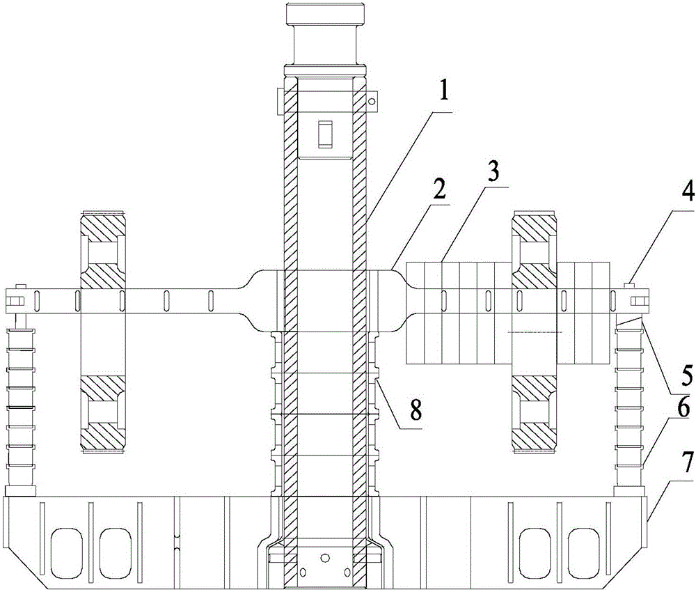
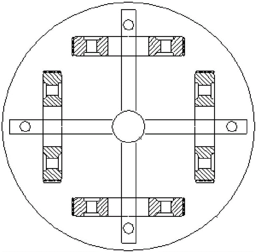
[0018] Such as figure 1 , 2 The gear quenching device shown includes a chassis 7, a boom 1 vertically installed in the center of the chassis 7, a cross-shaped cantilever fin beam 2 with a center hole in the center, the boom 1 passes through the center hole, and the cantilever fin beam A number of spacers 8 are stacked on the outer side of the boom 1 between 2 and the chassis 7, and the gears are symmetrically inserted on the cantilever wing beam 2. The four outer ends of the cantilever wing beam 2 are provided with peripheral holes. A vertical bracket 4 whose lower end is connected to the upper surface of the chassis 7 is penetrated in the hole. The vertical bracket 4 between the cantilever wing beam 2 and the chassis 7 is sleeved with a plurality of sleeves 6 stac...


PUM


Abstract

The invention relates to a gear quenching device. The gear quenching device comprises a chassis, a hanger rod perpendicularly mounted on the center of the chassis and a cantilever wing beam, wherein a plurality of spacer bushes are stacked at the outer side of the hanger rod between the cantilever wing beam and the chassis in a sleeving mode; peripheral holes are formed in four outer end parts of the cantilever wing beam; vertical brackets, lower ends of which are connected to the upper surface of the chassis, are formed in the peripheral holes in a penetrating mode; a plurality of sleeves are stacked at the outer side of the vertical brackets between the cantilever wing beam and the chassis in the sleeving mode; and a pair of wedge-shaped cushion blocks is blocked between the sleeves and the vertical brackets. The gear quenching device has the beneficial effects: a cross cantilever wing beam is adopted for suspending a gear, so that the advantages of high efficiency, stability, safety and the like are achieved; suspending, quenching and racking can be efficiently completed by regulating height of the space bushes and height of the cushion blocks, so that parts in the device are fixed and do not shift. Number of loaded gears is increased, so that production efficiency is greatly improved, and production cost is greatly reduced; and the left end and the right end of the gear are uniformly heated, so that the dimension precision of the gear is improved.

Description

Technical field [0001] The invention relates to a gear quenching device. Background technique [0002] Quenching is a metal heat treatment process that has just been heated to a certain temperature and then rapidly cooled in a cooling medium after heat preservation to change the surface or internal metallographic structure of the material to control its performance. The metal heat treatment process is an important process in mechanical manufacturing. . Locomotive gear is the basic work piece in mechanical transmission, and its quality, performance, and life span directly affect the performance index and operation of the vehicle. [0003] Gear processing is also a complex technical process in which cold and hot processing are intersected. It needs to be transformed and mounted during repeated heating and cooling processes. [0004] At present, deep pit furnaces generally use the cascade quenching method. The amount of furnace installed per quenching furnace is small, and the cascade...

Claims


Application Information

Patent Timeline
Patent Type & Authority Applications(China)
IPC IPC(8): C21D9/32C21D1/62
CPCC21D9/32C21D1/62
Inventor 胡静武计强许仁伟
Owner CHANGZHOU UNIV
Why Eureka
Try Eureka