
Draught fan fault monitoring system

A fault monitoring and fan technology, applied in signal transmission systems, mechanical equipment, machines/engines, etc., can solve problems such as complex wiring and difficult troubleshooting of fault points, avoid inconvenience, realize mobile monitoring, system improvement and convenience Effect

Inactive Publication Date: 2017-03-29
ZHEJIANG SCI-TECH UNIV
View PDF4 Cites 2 Cited by
  • Summary
  • Abstract
  • Description
  • Claims
  • Application Information

AI Technical Summary

Problems solved by technology

[0003] In order to solve the above technical problems, this application provides a wind turbine fault monitoring system, which connects the wind turbine site and the data processing terminal through wireless signals, thus eliminating the need for complex wired network wiring on the wind turbine site, thereby solving the problem of complex wiring and troubleshooting of difficult points of failure in wired networks

Method used


Image

  • Draught fan fault monitoring system

Examples


Embodiment Construction

[0014] In order to describe the technical solution provided by the present invention in more detail, further description will be made here in conjunction with the accompanying drawings.

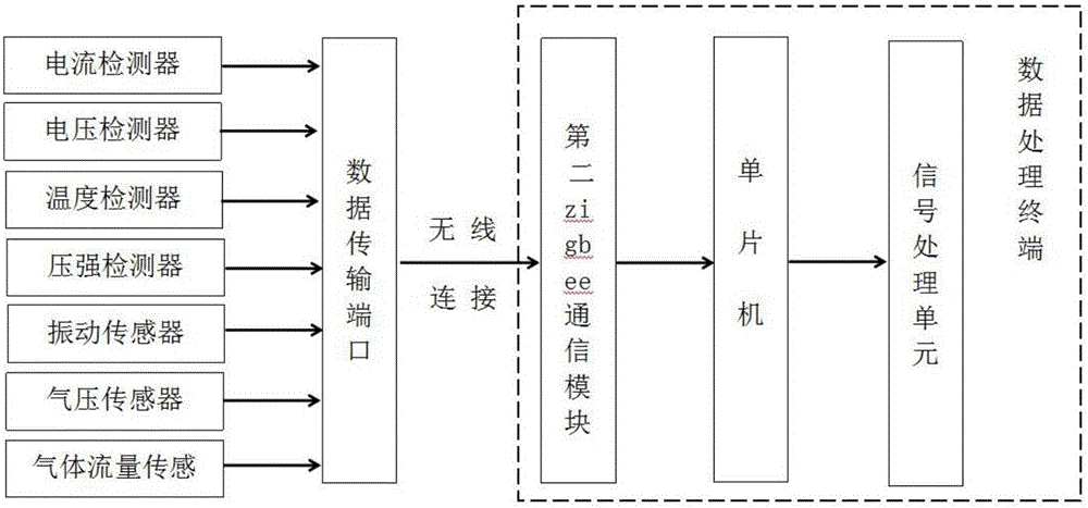
[0015] refer to figure 1 As shown, the fan fault monitoring system provided by this application includes a fan body installed on the fan work site, a sensor assembly installed on the fan body for collecting various states of the fan when it is working, and a sensor assembly installed on the fan body for A data transmission port for transmitting data and a data processing terminal for processing and displaying data information collected by sensor components; the sensor components include current detectors, voltage detectors, temperature detectors, pressure detectors, vibration sensors, air pressure sensors and a gas flow sensor; the data signal collected by the sensor assembly is uploaded to the data processing terminal in a wireless manner through the WI-FI networking port included in the dat...


PUM


Abstract

The invention discloses a draught fan fault monitoring system. The draught fan fault monitoring system comprises a draught fan body, a sensor assembly installed on the draught fan body, a data transmission port formed in the draught fan body, and a data processing terminal. The signal output end of the sensor assembly is connected with the signal input end of the data transmission port. The data transmission port is in communication connection with the data processing terminal. The sensor assembly comprises a current detector, a voltage detector, a temperature detector, a pressure intensity detector, a vibration sensor, an air pressure sensor and a gas flow sensor. The data transmission port comprises a WI-FI networking port and a first zigbee communication module. The data processing terminal comprises a second zigbee communication module in wireless communication connection with the first zigbee communication module, a single-chip microcomputer connected to the signal output end of the second zigbee communication module, and a signal processing unit connected to the signal output end of the single-chip microcomputer. By means of the draught fan fault monitoring system, the problem that removal of fault points in the wired network is difficult is solved.

Description

technical field [0001] The invention relates to a monitoring system, in particular to a fan failure monitoring system. Background technique [0002] At present, most of the monitoring of fan faults is carried out using wired network systems. The data transmission between the fan and the monitoring center is realized through complex wiring at the fan installation site, thereby realizing the monitoring of fan faults; the wired network system is used to detect fan faults. Monitoring can ensure the stability of data, but it requires complex wiring at the site where the wind turbine is located, and the entire line is complicated; in addition, troubleshooting the fault point of the line is also a relatively difficult task. Contents of the invention [0003] In order to solve the above technical problems, this application provides a wind turbine fault monitoring system, which connects the wind turbine site and the data processing terminal through wireless signals, thereby elimina...

Claims


Application Information

Patent Timeline
Patent Type & Authority Applications(China)
IPC IPC(8): F04D27/00G08C17/02
CPCG08C17/02F04D27/00
Inventor 赵新龙吴双江
Owner ZHEJIANG SCI-TECH UNIV
Learn More