Loading device for testing performance stability of servo valve

A technology of stability test and loading device, which is applied in the direction of servo meter circuit, fluid pressure actuation device, fluid pressure actuation system test, etc. It can solve the problems that the zero position stability and long-term working reliability of the servo valve cannot be assessed. , to achieve the effect of small friction, reduce motion resistance and increase friction torque

Inactive Publication Date: 2017-03-29
BEIJING JIAOTONG UNIV
View PDF8 Cites 6 Cited by
  • Summary
  • Abstract
  • Description
  • Claims
  • Application Information

AI Technical Summary

Problems solved by technology

[0003] The current static and dynamic test benches for servo valves only focus on testing the no-load flow characteristics and flow output response of servo valves, and cannot assess the zero position stability and long-term working reliability of servo valves.

Method used


Image

  • Loading device for testing performance stability of servo valve
  • Loading device for testing performance stability of servo valve
  • Loading device for testing performance stability of servo valve

Examples


Embodiment 1

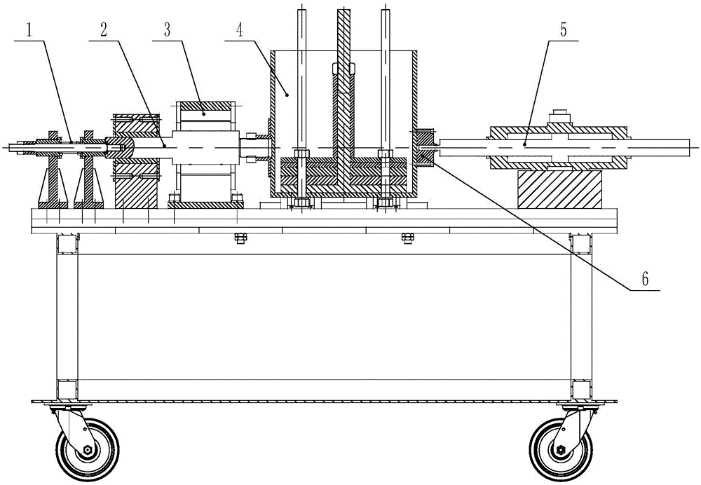
[0030] Such as figure 1 , The loading device for the performance stability test of the servo valve consists of five parts connected in sequence: elastic force loading realization mechanism 1; main shaft and support connection mechanism 2; friction force loading realization mechanism 3; inertial force loading realization mechanism 4; the servo mechanism under test 5.

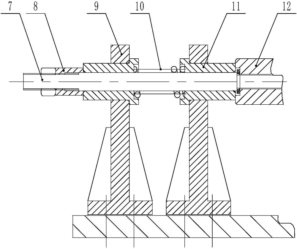
[0031] Such as figure 2 , the elastic force loading realization mechanism 1 is composed of a spring shaft 7 , a spring guide sleeve 11 , a spring seat 9 and a loading spring 10 .

[0032] The loading spring guide sleeve 11 is on the spring shaft 7, and the length of the spring can be adjusted according to the system requirements to provide the required elastic force; the loading spring 10 is set on the spring shaft 7, and the two ends are limited by the edge of the spring guide sleeve 11 , to prevent the radial movement and deformation of the spring; the spring sleeve 8 is installed in the hole of the spring s...

Embodiment 2

[0051] During the design process, the combined loading and separate loading of the three loading forces of elastic force, frictional force and inertial force are considered.

[0052] When combined loading, adjust the three force loading devices to set the value of the required loading force,

[0053] The friction force can be obtained from the known spring stiffness K and spring compression x,

[0054] f 弹 =K·x

[0055] The friction force can be based on the positive pressure F provided by the brake hydraulic cylinder 1 , the coefficient of friction μ gets

[0056] f 摩 = 2μ·F 1

[0057] The magnitude of the inertial force can be determined according to the number n of friction plates when the mass of a single friction plate is m and the acceleration is a.

[0058] f 惯 = n·m·a

[0059] Then the resultant force can be loaded on the servo mechanism, and the resultant force of the three loading forces can be obtained by using the collected value of the tension pressure se...


PUM


Abstract

The invention provides a loading device for testing performance stability of a servo valve. The loading device comprises an elastic force loading mechanism, a friction force loading mechanism, an inertia force loading mechanism, a tested servo mechanism, a main shaft and a support connection mechanism, wherein the elastic force loading mechanism is in threaded connection with the main shaft through a spring shaft; a friction plate of the friction force loading mechanism is coaxially matched with the main shaft; the left end of the inertia force loading mechanism is in threaded connection with the main shaft, and the right end of the inertia force loading mechanism is connected with a hydraulic cylinder piston rod. The loading device is used for loading the elastic force, the friction force and the inertia force of the servo valve so as to detect stability and reliability of performance of the servo valve under the load condition and particularly detect the zero-position stability of the servo valve; the hydraulic test condition of long-term operation of the servo valve is provided; through test of the product performance under long-term operation condition of the servo valve, the reliability of the product can be improved, so that the reliability of the product in the operation time can be ensured.

Description

technical field [0001] The invention relates to the field of load simulators, in particular to a loading device for a performance stability test of a servo valve. Background technique [0002] The load simulator is required to simulate the individual application and combined application of three load moments of inertia, friction, and elasticity. The load for regular tests is the combined force of inertia, friction, and elasticity, and the constant load is used for research tests. [0003] The current static and dynamic test benches for servo valves only focus on testing the no-load flow characteristics and flow output response of servo valves, and cannot assess the zero position stability and long-term working reliability of servo valves. Therefore, it is necessary to establish the performance stability and reliability test conditions of the servo valve, so as to correctly evaluate and quantify the performance stability and reliability of the long-term working servo valve, a...

Claims


Application Information

Patent Timeline
Patent Type & Authority Applications(China)
IPC IPC(8): F15B19/00
CPCF15B19/00F15B2211/855
Inventor 延皓李红岩董立静李长春张金英黄静姜帅琦
Owner BEIJING JIAOTONG UNIV
Why Eureka
Try Eureka