
Pipe connecting structure for metallurgical furnace and metallurgical furnace

A connection structure and metallurgical furnace technology, which is applied to non-detachable pipe connections, pipes/pipe joints/fittings, furnaces, etc., can solve problems such as separation of welds and weldments, water leakage at welds, and increased operating costs of metallurgical furnaces , to achieve the effect of improving weld quality, increasing connection strength and ensuring reliability

Inactive Publication Date: 2017-03-29
JIANGXI NERIN EQUIP
View PDF7 Cites 0 Cited by
  • Summary
  • Abstract
  • Description
  • Claims
  • Application Information

AI Technical Summary

Problems solved by technology

When the copper water jacket is used in a high-temperature, corrosive and dusty workplace, the temperature stress of the pipeline, the additional load of the external pipeline, the ambient temperature and corrosive gas and smoke can easily cause the separation of the weld and the weldment , causing water leakage at the weld, which endangers the safe and normal operation of the metallurgical furnace
[0004] The water leakage of the connection structure of the copper water jacket at the furnace mouth of the metallurgical furnace generally needs to be shut down to deal with it, which not only increases the operating cost of the metallurgical furnace, but also affects the normal service life of the refractory materials of the metallurgical furnace

Method used


Image

  • Pipe connecting structure for metallurgical furnace and metallurgical furnace
  • Pipe connecting structure for metallurgical furnace and metallurgical furnace
  • Pipe connecting structure for metallurgical furnace and metallurgical furnace

Examples


Embodiment Construction

[0033] Embodiments of the invention are described in detail below, examples of which are illustrated in the accompanying drawings. The embodiments described below by referring to the figures are exemplary and are intended to explain the present invention and should not be construed as limiting the present invention.

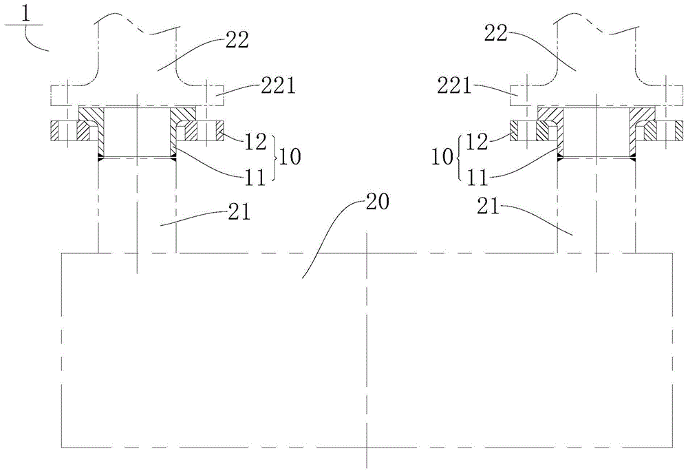
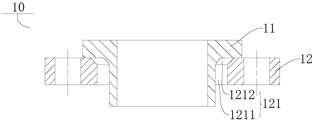
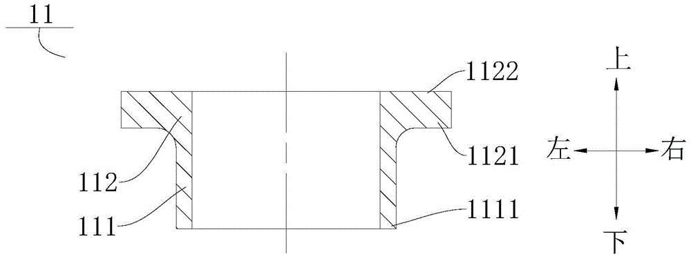
[0034] Refer below Figure 1-Figure 6 The pipe connection structure 10 for the metallurgical furnace 1 according to the embodiment of the present invention will be described in detail.

[0035] like Figure 1-Figure 6 As shown, the pipe connection structure 10 for the metallurgical furnace 1 according to the embodiment of the present invention includes: a communication body 11 .

[0036] Specifically, as figure 1 As shown, the communication body 11 can be formed into a tubular shape, and the communication body 11 is suitable for being connected between the first communication pipe 21 and the second communication pipe 22 of the metallurgical furnace 1, so that ...


PUM


Abstract

The invention discloses a pipe connecting structure for a metallurgical furnace and the metallurgical furnace. The pipe connecting structure comprises a communicating main body and a connecting piece; the communicating main body is connected between a first communicating pipe and a second communicating pipe of the metallurgical furnace; the end part of a first end of the communicating main body is manufactured by the same materials with the first communicating pipe, and is welded with the first communicating pipe; and the end surface of a second end, opposite to the first end, of the communicating main body is tightly connected with the second communicating pipe. In the pipe connecting structure for the metallurgical furnace, as the end part of the first end of the communicating main body is manufactured by the same materials with the first communicating pipe, and is welded with the first communicating pipe, the welding line quality of the communicating body and the first communicating pipe is improved, and the welding line connecting strength is enhanced; and in addition, the end surface of the second end, opposite to the first end, of the communicating main body is tightly connected with the second communicating pipe, so that the sealing reliability can be guaranteed to prevent leakage.

Description

technical field [0001] The invention relates to the technical field of metallurgical equipment, in particular to a pipe connection structure for a metallurgical furnace and the metallurgical furnace. Background technique [0002] The connection between the first connecting pipe of the copper water jacket for metallurgical furnace and the second connecting pipe of the external pipeline is usually threaded connection or socket welding flange connection with neck. When the first connecting pipe and the second connecting pipe of the copper water jacket are connected by threads, because the second connecting pipe in the pipeline is a steel piece, the thermal expansion of the steel piece and the copper pipe are different. When the copper water jacket is used in an environment of In high-temperature, corrosive and dusty workplaces, the connecting thread at the end of the first connecting pipe is easily deformed and damaged, and the copper water jacket will leak at the threaded conn...

Claims


Application Information

Patent Timeline
IPC IPC(8): F27D9/00F16L13/02
Inventor 陈少武
Owner JIANGXI NERIN EQUIP
Learn More