Welding process of nodular cast iron pipe flange pipe

A ductile iron pipe and welding process technology, applied in welding equipment, welding/welding/cutting items, manufacturing tools, etc., can solve the problems affecting the quality of ductile iron pipe welding flange pipes, and achieve improved weld strength and savings The effect of time and weld quality improvement

Inactive Publication Date: 2020-06-05
HUBEI POLYTECHNIC UNIV
View PDF6 Cites 0 Cited by
  • Summary
  • Abstract
  • Description
  • Claims
  • Application Information

AI Technical Summary

Problems solved by technology

[0003] The technical problem to be solved by the present invention is to provide a ductile iron pipe flange pipe welding process, which aims to solve the technical problem in the prior art that the quality of the ductile iron pipe welded flange pipe is affected by the low quality of the weld seam

Method used


Image

  • Welding process of nodular cast iron pipe flange pipe
  • Welding process of nodular cast iron pipe flange pipe
  • Welding process of nodular cast iron pipe flange pipe

Examples


Embodiment 1

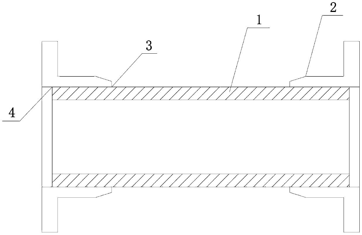
[0024] combine Figure 1 to Figure 3 ,as well as Figure 8 Shown is the first specific embodiment of a ductile iron pipe flange pipe welding process of the present invention, the process mainly includes the following steps:

[0025] Step 1): Cut the ductile iron pipe 1 into a certain length with a gantry cutting machine.

[0026] Step 2): After heating the flange 2 to above 500°C, specifically, it can be heated to 650-800°C, and perform shrink-fit interference fit with the ductile iron pipe 1 to complete the installation. The structural diagram of the installation is as follows figure 1 As shown, there is an outer gap 3 and an inner gap 4 between the ductile iron pipe 1 and the flange 2 .

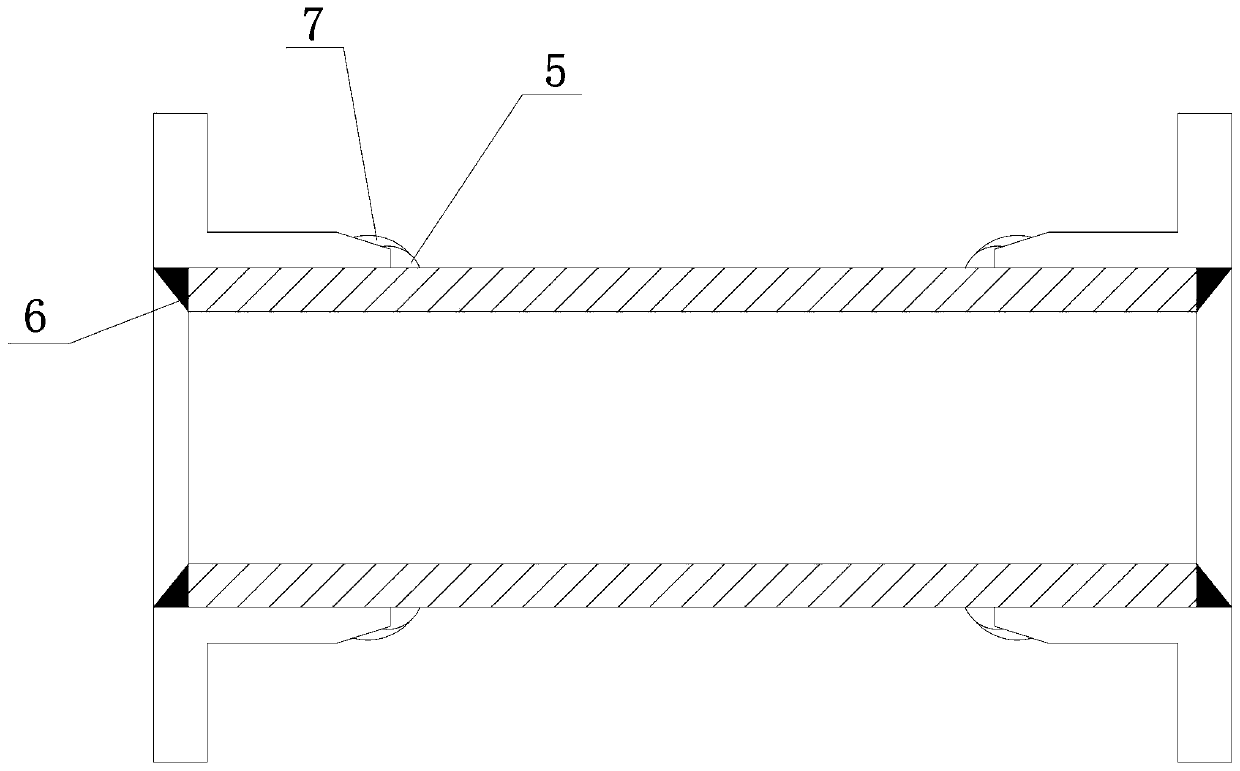
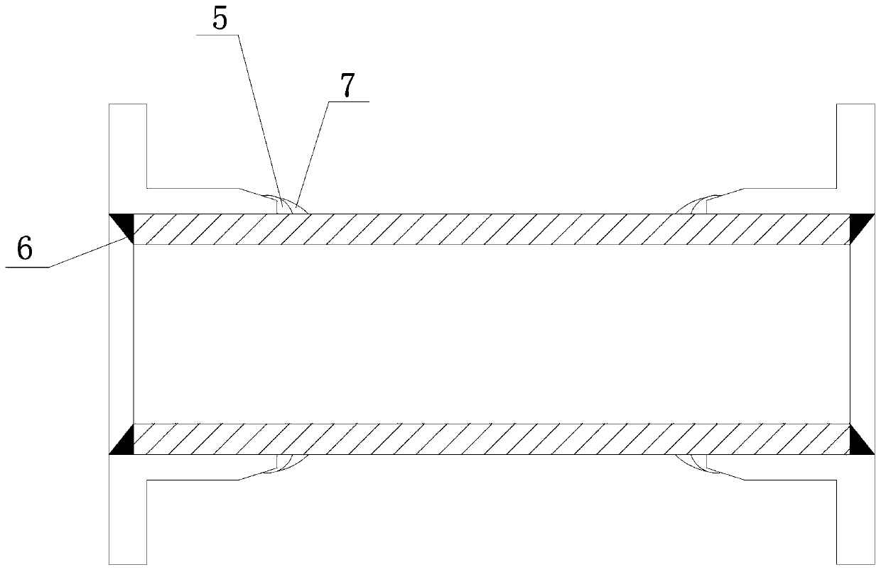
[0027] Step 3): Using Ar and CO 2 The mixed gas is used as the shielding gas, and the outer gap 3 and the inner gap 4 are welded for the first time with a welding torch, and the welding is carried out at the same time under the condition of 50-60min / turn. In this embodiment, it is specif...

Embodiment 2

[0031] In this example, combined with Figure 4 to Figure 7 As shown, the difference from the first embodiment is that the second welding also includes a third welding on the outer gap 3 to form a third outer bead 8 .

[0032] Such as Figure 4 Shown is a schematic diagram of the structure of the first product of this embodiment, wherein the third outer bead 8 is bonded to the ductile iron pipe 1 and the first outer bead 5, the second outer bead 7 and the third outer bead 8 Cover the first outer bead 5 from the root of the weld toe to the weld seam.

[0033] Such as Figure 5 Shown is a schematic diagram of the structure of the second product of this embodiment, wherein the third outer bead 8 is bonded to the ductile iron pipe 1, and the first outer bead 5 is bonded to the second outer bead 7, and the second outer bead 7 And the third outer bead 8 completely covers the first outer bead 5 from the root of the weld toe to the weld seam.

[0034] Such as Figure 6 Shown is a...


PUM


Abstract

The invention discloses a welding process of a nodular cast iron pipe flange pipe. The welding process comprises the following steps: (1) cutting a nodular cast iron pipe into a certain length; (2) heating a flange and performing shrinkage fit and interference fit on the flange and the nodular cast iron pipe to finish installation; (3) using a mixed gas of Ar and CO2 as a protective gas, and simultaneously performing primary welding on an inner gap and an outer gap by using a welding gun to form a first outer welding bead and an inner welding bead; and (4) welding the outer gap for the secondtime, specifically, at least one welding is included to form at least two outer welding beads including the first outer welding bead, the first outer welding bead is positioned between the nodular cast iron pipe and the flange, the other outer welding beads are attached to the nodular cast iron pipe or the flange and the at least one outer welding bead, and the welding angle alpha between the axisof the welding gun and the longitudinal vertical line is 30-35 degrees during the primary welding and the secondary welding; and the secondary welding is carried out under the condition of 15-25 min / circle, and the multiple outer welding beads are finally formed. The welding process can obviously improve the welding seam quality and obviously improve the welding seam strength, thereby improving the welding seam quality of welded pipe fittings.

Description

technical field [0001] The invention relates to a flange pipe welding process of nodular cast iron pipes. Background technique [0002] With the rapid development of modern society, the demand for ductile iron welded flange pipes in domestic and foreign markets is rapidly increasing. As a substitute for gray cast iron pipes and other pipes, ductile iron flange pipes have excellent corrosion resistance, good ductility, and The advantages of good sealing effect and easy installation are widely used in municipal, industrial and mining enterprises for water supply, gas transmission, oil transportation and other fields. In the prior art, the ductile iron pipe and the flanged pipe are usually sealed with inner and outer double-pass girth welds. Since there are only two weld passes, the welding angle is generally 45° during the welding process, and the weld seam The molten pool is usually only 2mm, and the weld seam is prone to problems such as weak weld seam strength, not full we...

Claims


Application Information

Patent Timeline
IPC IPC(8): B23P15/00B23K31/02B23K101/06B23K103/06
CPCB23K31/02B23P15/00B23K2101/06B23K2103/06
Inventor 赵琼徐超
Owner HUBEI POLYTECHNIC UNIV
Why Eureka
Try Eureka