Optical system for panoramic imaging

An optical system and panoramic imaging technology, applied in the field of optical systems for panoramic imaging, can solve the problems of high safety distance, waste of resources, complicated debugging, etc., and achieve the effect of close safety distance, easy installation and cost reduction.

Inactive Publication Date: 2017-03-29
河森堡(深圳)科技有限公司
View PDF10 Cites 3 Cited by
  • Summary
  • Abstract
  • Description
  • Claims
  • Application Information

AI Technical Summary

Problems solved by technology

[0004] (1) The amount of raw data is huge, multiple cameras require multi-channel image processing, and the cost increases exponentially;
[0005] (2) Due to the use of multiple cameras or lenses, there are obvious seams during stitching, and it is difficult to achieve synchronization of white balance and frame rate between multiple cameras;
[0007] (4) Shooting and post-production are extremely complicated and costly
[0009] (1) Like the splicing type, there are also problems such as seams, difficulty in synchronization, and excessive safety distance;
[0010] (2) Multiple cameras need to process a large amount of data, and it is difficult to achieve in-camera restoration and calculation;
[0011] (3) There is a bottleneck in multiple cameras
[0013] (1) The viewing angle is single, there are dead angles, and the cooperation of multiple devices is required;
[0014] (2) Multi-device collaboration leads to data fragmentation and large error values;
[0015] (3) The viewing angle of mobile monitoring equipment is limited, and the observation efficiency is limited
[0017] (1) The position and angle of the camera are fixed and cannot be moved and adjusted;
[0018] (2) The shooting angle of view is limited, and distant members are blocked or cannot be photographed clearly;
[0019] (3) The shooting area is limited and cannot cover all venues
[0021] (1) The multi-eye or fish-eye splicing scheme has many devices and high power consumption;
[0022] (2) It needs a cloud platform and multiple devices, which is complicated and heavy;
[0023] (3) Occupying too much of the limited resources and load of the UAV itself;
[0024] (4) Anti-shake compensation cannot be performed
[0026] (1) Traditional robots require multiple cameras to work together, resulting in a large amount of power consumption and troubleshooting
[0027] (2) Moving parts are required to move the viewing angle, and the structure and function are backward
[0028] (3) The function is limited by the viewing angle and sensor, and the interactive recognition is slow
[0031] (2) Most crews already have ordinary SLRs and need to purchase panoramic cameras again, which is a waste of resources;
[0032] (3) The CMOS and optical quality of existing panoramic cameras cannot be compared with traditional SLR manufacturers; and the shooting equipment that uses multiple SLR cameras is bulky, has a large safety distance, and is complex to debug
[0034] (1) If mobile phones, tablets and other devices need to take panoramic photos, the mobile phone needs to be moved horizontally to take panoramic photos. The shooting speed is slow and the subject is not allowed to move;
[0035] (2) Laptops and desktop computers are limited by the camera and cannot take panoramic shots

Method used


Image

  • Optical system for panoramic imaging
  • Optical system for panoramic imaging
  • Optical system for panoramic imaging

Examples


Embodiment 1

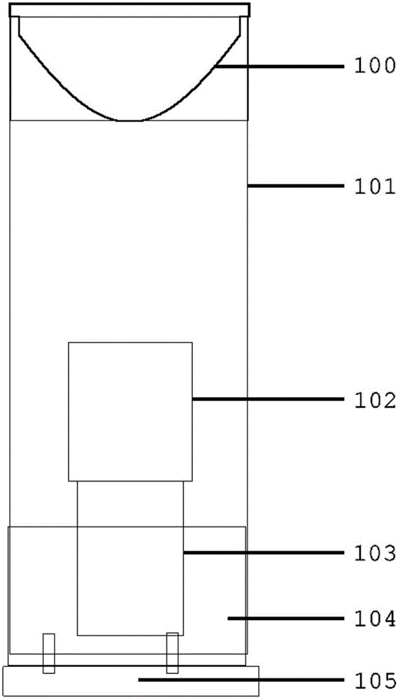
[0098] This embodiment is an example of a typical panoramic camera solution, specifically, it can be directly adopted figure 1 Image capture is performed with the optical system for panoramic imaging described in . A single camera can be used to collect panoramic images, there is no multi-channel image processing, no post-splicing, no multi-camera synchronization problems, and no blind spots, so a very short safe distance can be achieved, effectively making the entire panoramic imaging system Miniaturization and light weight reduce system cost and improve shooting quality. In addition, due to the use of a single lens, the complexity of the restoration algorithm is low, and the restoration and unlocking can be carried out in the built-in ARM chip or FPGA, DSP chip, thereby realizing the restoration solution in the camera.

Embodiment 2

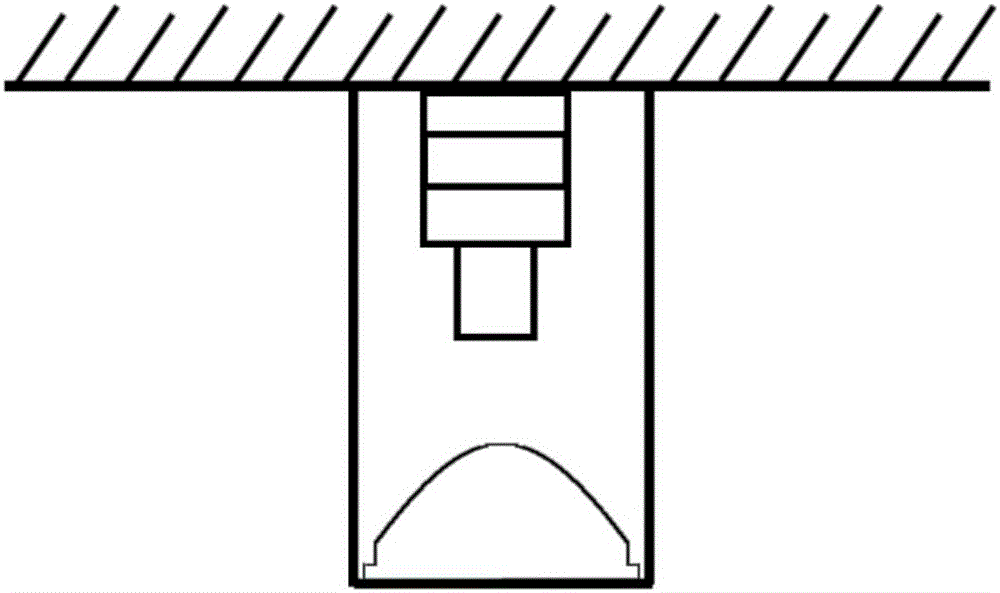
[0100] In this embodiment, the optical system of panoramic imaging is used in the field of security monitoring, and the optical system of panoramic imaging in the present invention is arranged in the area that needs security monitoring, such as image 3 , and communicate with the monitoring terminal in the remote monitoring center through the communication interface through the communication network, which can realize the setting of any position in the optional space and realize the panoramic observation without dead angle. When used in installed monitoring equipment, it can be connected with the installed equipment lens interface according to the Figure 4 The combination of methods enables panoramic monitoring without the need for complex upgrades to monitoring equipment, which saves costs and makes the overall equipment lighter.

Embodiment 3

[0102] In this embodiment, the panoramic imaging optical system is used in the teleconferencing field, and the panoramic imaging optical system in the present invention is arranged at any position in the remote conference venue, and the acquired conference venue is obtained through the communication network through the communication interface. Real-time images are displayed on the display screen in the meeting place in real time, and are transmitted to the remote party in the teleconference in time. The optical system of the panoramic imaging in the present invention is not limited by the venue because it is a 360° panoramic shooting, and can be used in the meeting place according to the situation It can be placed freely and all members and facilities can be displayed.


PUM


Abstract

The invention discloses an optical system for panoramic imaging. The optical system specifically comprises a reflector, a light transmission window, a lens, a camera, a mainboard, a battery and a base; and a communication interface used for sending a panoramic image or a panoramic video to external output equipment is below the base. The invention further discloses a working method of the optical system for panoramic imaging. Because the panoramic image can be acquired by using the single camera, multi-channel image processing and late stitching are unnecessary; the problems of multi-camera synchronization, blind spot cracks and edge distortion can be avoided; and furthermore, the logical difficulty of a reductive algorithm is greatly reduced.

Description

technical field [0001] The invention relates to the fields of video acquisition, engineering optics, and electromechanical integration, and in particular to an optical system for panoramic imaging. Background technique [0002] Existing panoramic shooting methods are mainly divided into splicing and fisheye methods. [0003] Among them, the splicing type requires more than 2 cameras, and its disadvantages are: [0004] (1) The amount of raw data is huge, multiple cameras require multi-channel image processing, and the cost increases exponentially; [0005] (2) Due to the use of multiple cameras or lenses, there are obvious seams during stitching, and it is difficult to achieve synchronization of white balance and frame rate between multiple cameras; [0006] (3) A large safety distance is required, and the object to be photographed cannot be too close to the camera; [0007] (4) Shooting and post-production are extremely complicated and costly. [0008] A typical fisheye...

Claims


Application Information

Patent Timeline
Patent Type & Authority Applications(China)
IPC IPC(8): G03B37/00G02B13/00G02B5/10
CPCG02B13/00G03B37/00G02B5/10
Inventor 伍兴云
Owner 河森堡(深圳)科技有限公司
Why Eureka
Try Eureka