

Climbing-free winding and tying device for transmission line tree barrier cutting
A transmission line and tree barrier technology, which is applied in the field of transmission line tree barrier felling, free-climbing tree winding and tethering device, can solve the problems of cleaning personnel such as high labor intensity, falling from high altitude, and easy electric shock, so as to improve the efficiency of live maintenance, The effect of ensuring safe and reliable operation and reducing the probability of accidents
- Summary
- Abstract
- Description
- Claims
- Application Information
AI Technical Summary
Problems solved by technology
Method used
Image

Examples
Embodiment Construction
[0019] The preferred embodiments of the present invention will be described in detail below with reference to the accompanying drawings.
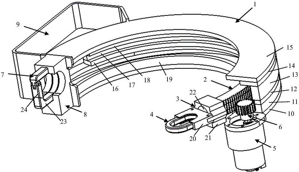
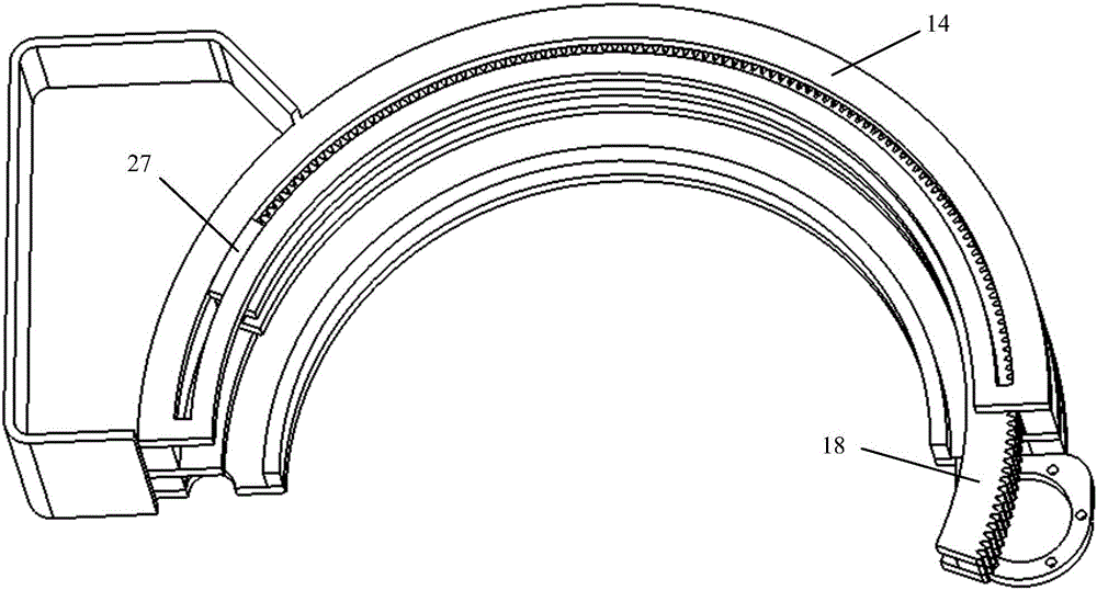
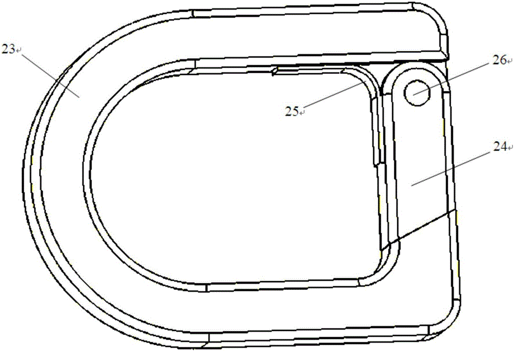
[0020] A power transmission line tree barrier felling free climbing tree winding tether device, comprising a hoop shell 1, a hoop core 2, a ring fixing mechanism 3, a ring 4, a reduction motor 5, a pinion 6, a ring buckle 7, and a ring Buckle the fixed block 8 and the battery circuit box 9, the hoop shell 1 is formed by laminations 11, 12, 13, 14, 15 and 19 connected by bolts; 18 is superimposed through bolt connection, with a rope groove in the middle, and the hoop shell and hoop core form a rope feeding mechanism that moves along a fixed track; the ring fixing mechanism is composed of a ring groove 20, a ring groove fixing block 21 And electromagnet 22 forms; Described ring buckle is made up of button body 23, block 24, leaf spring 25 and ring buckle pin 26; Form buckle ring mechanism by ring buckle and ring.
[0021] The top layer 18 of...
PUM
 Abstract
Description
Claims
Application Information