
Laser phase noise elimination device, system and method

A phase noise and laser technology, which is applied in the direction of testing optical performance and reducing undesired effects, can solve the problem of low spatial resolution and achieve the effect of improving spatial resolution

Inactive Publication Date: 2017-04-05
ZTE CORP
View PDF6 Cites 8 Cited by
  • Summary
  • Abstract
  • Description
  • Claims
  • Application Information

AI Technical Summary

Problems solved by technology

[0008] The present invention provides a laser phase noise elimination device, system and method to at least solve the problem of low spatial resolution of long-distance measurement by optical frequency domain reflectometer technology in the related art

Method used


Image

  • Laser phase noise elimination device, system and method
  • Laser phase noise elimination device, system and method
  • Laser phase noise elimination device, system and method

Examples


Embodiment Construction

[0029] Hereinafter, the present invention will be described in detail with reference to the drawings and examples. It should be noted that, in the case of no conflict, the embodiments in the present application and the features in the embodiments can be combined with each other.

[0030] It should be noted that the terms "first" and "second" in the description and claims of the present invention and the above drawings are used to distinguish similar objects, but not necessarily used to describe a specific sequence or sequence.

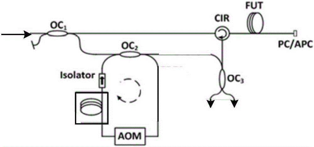
[0031] This embodiment provides a laser phase noise elimination device, figure 1 is a structural block diagram of a laser phase noise elimination device according to an embodiment of the present invention, such as figure 1 As shown, the device includes a Mach-Zehnder interferometer. In addition, the device also includes: a fiber delay loop (OFDL), wherein the fiber delay loop is coupled to the Mach-Zehnder interferometer through a first optical couple...


PUM


Abstract

The invention provides a laser phase noise elimination device, system and method. The device comprises a Mach-Zehnder interferometer and a fiber delay loop. The fiber delay loop is coupled on the reference arm of the Mach-Zehnder interferometer through a first optical coupler. The fiber delay loop comprises a series connected acousto-optic modulator and a delay fiber of the preset length, wherein the preset length is not greater than the coherent length of the laser. With application of the laser phase noise elimination device, system and method, the problem that the optical frequency domain reflectometer technology has low spatial resolution for long distance measurement in the relevant technology can be solved so that the spatial resolution of the optical frequency domain reflectometer technology for long distance measurement can be enhanced.

Description

technical field [0001] The invention relates to the field of optical fiber detection, in particular to a laser phase noise elimination device, system and method. Background technique [0002] In recent years, optical reflectometer technology has attracted increasing attention due to its ability to realize distributed measurements. It mainly includes Optical Time Domain Reflectometer (OTDR for short) and Optical Frequency Domain Reflectometer (OFDR for short). Among them, OTDR technology is widely used because it is relatively simple to implement and can realize long-distance distributed measurement. However, the spatial resolution of OTDR technology can only reach the meter level, which limits its application in some fields with high spatial resolution requirements, such as aerospace and building health monitoring. In contrast, the spatial resolution of OFDR technology can reach the order of centimeters, but its detection distance is limited by the coherence length of the ...

Claims


Application Information

Patent Timeline
IPC IPC(8): G01D3/028
CPCG01D3/028G01M11/02
Inventor 何祖源樊昕昱郭勇朱松林印永嘉刘庆文马麟杜江兵王彬
Owner ZTE CORP
Learn More