Drive control method and drive control circuit

A drive control circuit, drive control technology, applied in the direction of control/adjustment system, electrical components, adjustment of electrical variables, etc., can solve the problem of large loss of asymmetrical half-bridge flyback converters, etc., to improve light load efficiency and improve efficiency , the effect of reducing the volume

Inactive Publication Date: 2017-04-05
MORNSUN GUANGZHOU SCI & TECH
View PDF7 Cites 14 Cited by
  • Summary
  • Abstract
  • Description
  • Claims
  • Application Information

AI Technical Summary

Problems solved by technology

[0012] In view of this, the present invention will solve the problem that the above-mentioned asymmetrical half-bridge flyback converter has a large loss when outputting light load and no-load, and provides a method to reduce the loss of the asymmetrical half-bridge flyback converter when outputting light load and no-load. The drive control method of low loss makes the circuit structure simple, the output voltage ripple is small at no-load, and it is easy to realize and practical

Method used


Image

  • Drive control method and drive control circuit
  • Drive control method and drive control circuit
  • Drive control method and drive control circuit

Examples


no. 1 example

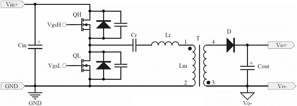
[0071] Figure 3-1 It shows the circuit principle block diagram of the asymmetrical half-bridge flyback converter of the first embodiment of the present invention. The present invention is an improvement on the control strategy based on the prior art, which is called the light-load up-conversion control mode here asymmetrical half-bridge flyback converter. like Figure 3-1 As shown, the asymmetrical half-bridge flyback converter in the light-load up-conversion control mode includes a flyback circuit and a drive control circuit; the flyback circuit includes a primary side circuit and a secondary side output rectification filter circuit, and the primary side circuit consists of a filter capacitor Cin, The resonant capacitor Cr, the main switch tube QH, the clamp switch tube QL are connected with the primary winding of the transformer T; the secondary side output rectification filter circuit is connected with the rectifier diode D and the filter capacitor Cout; the drive control...

no. 2 example

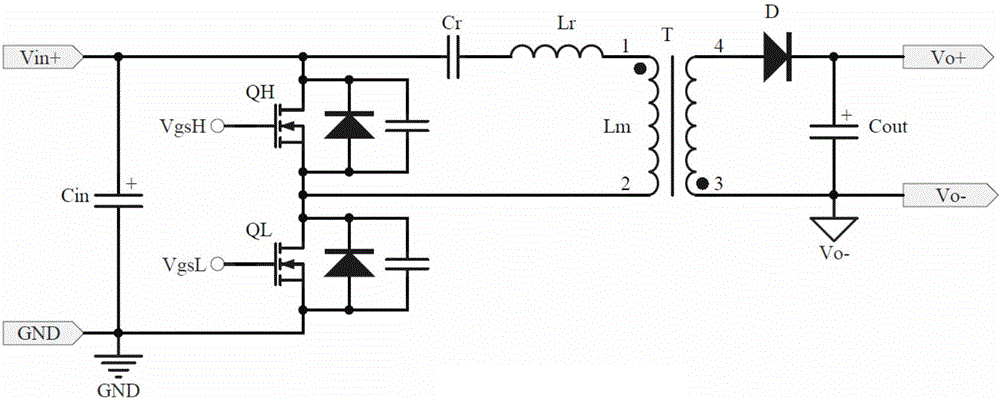
[0078] like Figure 3-2 As shown, it is the circuit principle block diagram of the second embodiment of the asymmetrical half-bridge flyback converter in the light-load up-conversion control mode of the present invention. The difference from the first embodiment is that the upper transistor QH is a clamp switch transistor, and the lower transistor QL is The main switching tube, the control effects of the two circuits are similar, but the connection positions of each module are reversed accordingly.

no. 3 example

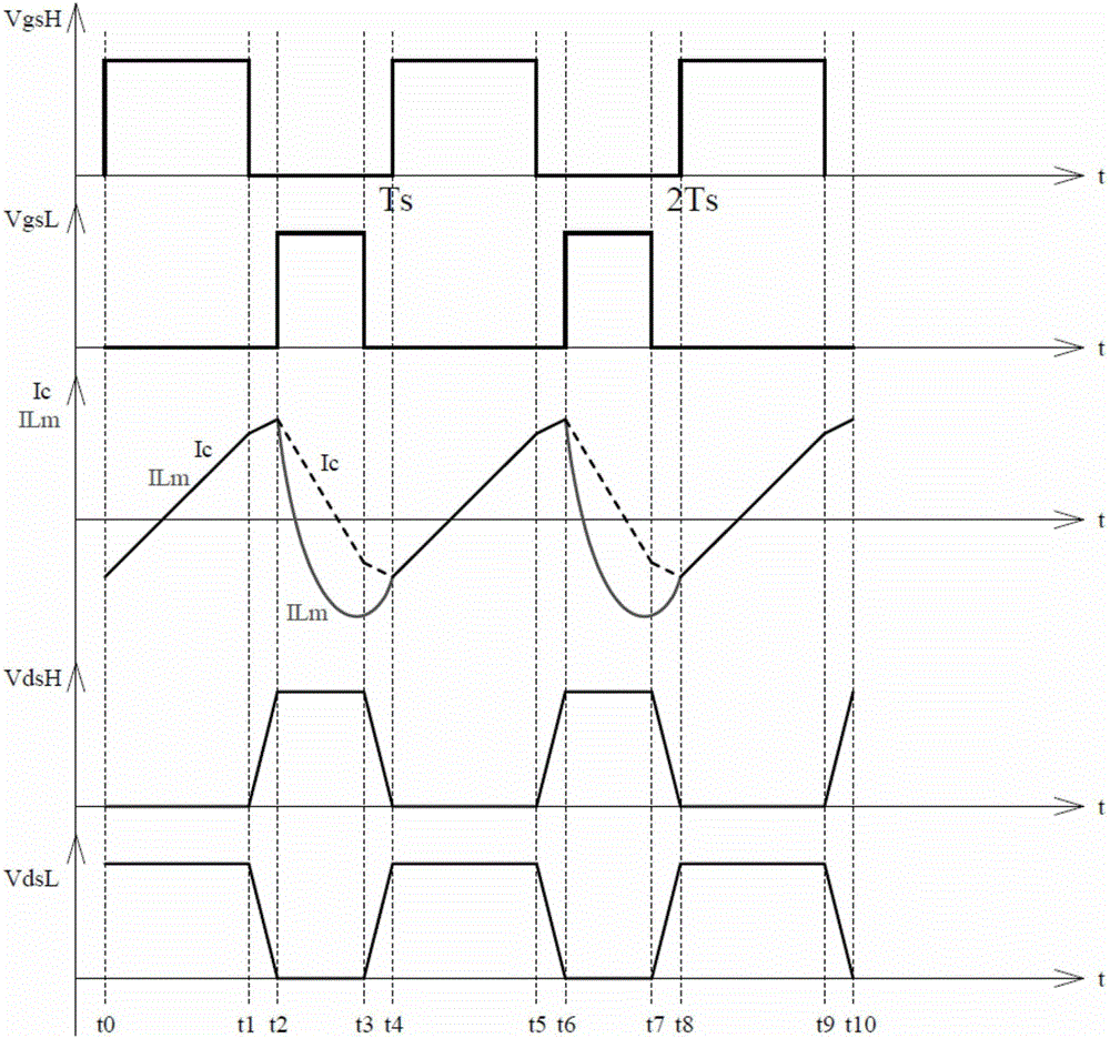
[0080] like Pic 4-1 As shown, it is the circuit of the third embodiment of the asymmetrical half-bridge flyback converter of the light-load up-conversion control mode of the present invention, which is the specific implementation circuit of the first embodiment of the present invention, and the dotted box 401 is the third embodiment of the present invention example of the drive control circuit, with Figure 4-3 As shown, a drive control circuit includes a drive control module and a light load detection control circuit. The drive control module is used for drive control of the transistor. The transistor includes a main switch tube and a clamp switch tube, wherein the drive control module adopts the main control chip , including the frequency adjustment terminal RT, the frequency adjustment terminal RT is grounded through the resistance Rt, and is used to set the operating frequency of the main control chip IC through the resistance Rt; the light load detection control circuit ...


PUM


Abstract

The invention provides a drive control method and drive control circuit with the object of reducing the loss of asymmetrical half-bridge fly-back converters in outputting light load or no load wherein the drive control circuit comprises a drive control module used to realize drive control over a transistor. The transistor consists mainly of a main switch tube and a clamp switch tube as well as a light load detection control circuit. The light load detection control circuit comprises a feedback signal control module and a frequency control module wherein the feedback signal control module detects the output load of a switch converter, compares the output load signal of the switch converter to see if it is lower than a set load point or not and outputs the comparison result of the detection value to the frequency control module. The frequency control module, based on the comparison result, maintains or raises the working frequency of the drive control module. That means if it is not light load, the working frequency of the drive control module stays unchanged. And if it is light load, the working frequency of the drive control module is raised.

Description

technical field [0001] The invention relates to the field of switching converters, in particular to a drive control method and a drive control circuit for an asymmetrical half-bridge flyback switching converter. Background technique [0002] With the rapid development of the field of power electronics, switching converters are used more and more widely, especially people put forward more requirements for switching converters with high power density, high reliability and small size. Generally, traditional low-power switching converters are implemented with flyback topology, which has the advantages of simple structure and low cost; however, ordinary flyback topology is hard switching, and cannot recover leakage inductance energy, thus limiting the efficiency and efficiency of small and medium power converters. volume. In order to meet the development trend of miniaturization, light weight and modularization of power converters, soft switching technology has become one of the...

Claims


Application Information

Patent Timeline
Patent Type & Authority Applications(China)
IPC IPC(8): H02M1/08H02M3/335H02M1/14
CPCH02M1/08H02M1/14H02M3/33523
Inventor 郑仁闪金若愚
Owner MORNSUN GUANGZHOU SCI & TECH
Why Eureka
Try Eureka