Multi-stage stirrer

A technology for mixers and stirring motors, which is applied to mixer accessories, mixers with rotating agitation devices, mixers, etc., which can solve the problem of difficulty in achieving uniform shearing and rapid mixing at the same time, poor sound insulation, and inability to continuously mix and discharge materials. And other problems, to achieve good sound insulation effect, good sealing, anti-corrosion effect

Inactive Publication Date: 2017-04-19
CHENGDU YITIAN TECH CO LTD
View PDF0 Cites 4 Cited by
  • Summary
  • Abstract
  • Description
  • Claims
  • Application Information

AI Technical Summary

Problems solved by technology

Due to the large difference in the characteristics of the stirred zone and the non-stirred zone, it is difficult to achieve the requirements of uniform shearing and rapid mixing in ordinary mixers
For example, the up-and-down and rotary agitator, the forward-reversing and up-and-down composite agitator all have very good mixing behavior, but their shear distribution is extremely uneven; a shortcoming of future technologies is that most of them are first-stage Stirring, uneven stirring, continuous stirring and discharging, and the sound insulation effect of the existing mixing equipment is not very good
These devices are not well suited for applications requiring both uniform shear and good mixing due to their good behavior in only one aspect

Method used


Image

  • Multi-stage stirrer
  • Multi-stage stirrer

Examples


Embodiment 1

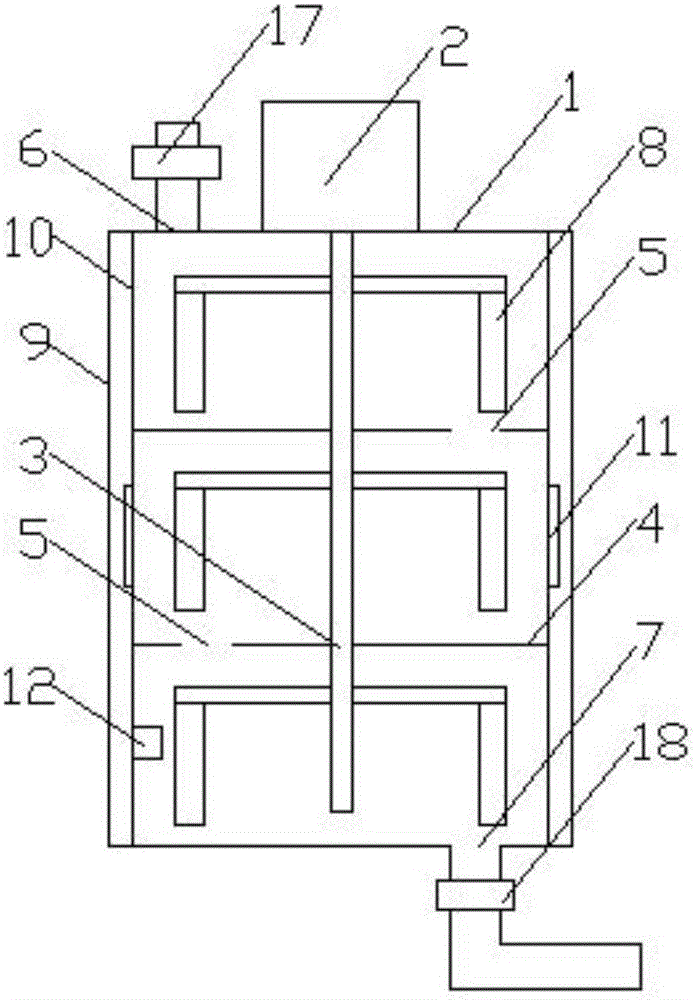
[0023] like figure 1 , figure 2 Shown, a kind of multi-stage mixer, comprises casing 1 and is arranged on the stirring motor 2 above casing, and the rotating shaft 3 of described stirring motor 2 is arranged in described casing 1; Described casing 1 is from top to The bottom is divided into multi-layer compartments, and the partition plate 4 of each compartment is provided with a discharge port 5, the top of the casing 1 is provided with a feed port 6, and the bottom of the casing 1 is provided with a total discharge port 7 , the feed port 6, the discharge port 5 and the total discharge port 7 are arranged in a bow shape; the rotating shaft 3 in each layer of the compartment is provided with a stirring impeller 8; the casing 1 includes an outer wall 9 and Inner wall 10, a plurality of temperature regulating devices 11 are distributed circumferentially between the outer wall 9 and the inner wall 10; a temperature sensor 12 is arranged in the lowest compartment of the casing 1...

Embodiment 2

[0025] like figure 1 , figure 2 Shown, a kind of multi-stage mixer, comprises casing 1 and is arranged on the stirring motor 2 above casing, and the rotating shaft 3 of described stirring motor 2 is arranged in described casing 1; Described casing 1 is from top to The bottom is divided into multi-layer compartments, and the partition plate 4 of each compartment is provided with a discharge port 5, the top of the casing 1 is provided with a feed port 6, and the bottom of the casing 1 is provided with a total discharge port 7 , the feed port 6, the discharge port 5 and the total discharge port 7 are arranged in a bow shape; the rotating shaft 3 in each layer of the compartment is provided with a stirring impeller 8; the casing 1 includes an outer wall 9 and Inner wall 10, a plurality of temperature regulating devices 11 are distributed circumferentially between the outer wall 9 and the inner wall 10; a temperature sensor 12 is arranged in the lowest compartment of the casing 1...

Embodiment 3

[0028] like figure 1 , figure 2 Shown, a kind of multi-stage mixer, comprises casing 1 and is arranged on the stirring motor 2 above casing, and the rotating shaft 3 of described stirring motor 2 is arranged in described casing 1; Described casing 1 is from top to The bottom is divided into multi-layer compartments, and the partition plate 4 of each compartment is provided with a discharge port 5, the top of the casing 1 is provided with a feed port 6, and the bottom of the casing 1 is provided with a total discharge port 7 , the feed port 6, the discharge port 5 and the total discharge port 7 are arranged in a bow shape; the rotating shaft 3 in each layer of the compartment is provided with a stirring impeller 8; the casing 1 includes an outer wall 9 and Inner wall 10, a plurality of temperature regulating devices 11 are distributed circumferentially between the outer wall 9 and the inner wall 10; a temperature sensor 12 is arranged in the lowest compartment of the casing 1...


PUM


Abstract

The invention discloses a multi-stage stirrer. The multi-stage stirrer comprises a machine shell and a stirring motor located on the upper side of the machine shell. A rotating shaft of the stirring motor is arranged inside the machine shell. The machine shell is divided into multiple partition chambers from up to bottom. A partition plate of each partition chamber is provided with a discharging opening. The top of the machine shell is provided with a feeding opening. The bottom of the machine shell is provided with a master discharging opening. The feeding opening, the discharging openings and the master discharging opening are distributed in a shape like the Chinese character 'gong'. The portion, located in each partition chamber, of the rotating shaft is provided with a stirring impeller. The machine shell comprises an outer wall and an inner wall. Multiple temperature adjusting devices are circumferentially distributed between the outer wall and the inner wall. A temperature sensor is arranged in the lowest partition chamber of the machine shell. The outer wall sequentially comprises a stainless steel layer, an acoustic-absorbing cotton layer, a cellular board layer and an acoustic-absorbing coating layer from inside to outside. The feeding opening is provided with a flow meter. The master discharging opening is provided with an electromagnetic valve. The multi-stage stirrer is simple in structure, adjustable in temperature, good in sound insulating effect and capable of achieving multiple stages of stirring and a good raw material stirring effect.

Description

technical field [0001] The invention relates to the field of raw material mixing machinery, in particular to a multistage mixer. Background technique [0002] The mixer occupies a large proportion in the chemical industry and the construction industry. Its role is mainly to provide a place for material mixing or chemical reaction. For this reason, the device is often required to have uniform shear distribution and good mixing behavior. Such as multi-phase dispersion system, multi-phase polymerization system, etc. that need to control the particle size. Due to the large difference in the characteristics of the stirred zone and the non-stirred zone, it is difficult to achieve the requirements of uniform shearing and rapid mixing in a common mixer. For example, the up-and-down and rotary agitator, the forward-reversing and up-and-down composite agitator all have very good mixing behavior, but their shear distribution is extremely uneven; a shortcoming of future technologies is...

Claims


Application Information

Patent Timeline
Patent Type & Authority Applications(China)
IPC IPC(8): B01F7/18B01F15/02B01F15/04B01F15/00
CPCB01F27/191B01F27/90B01F35/512B01F35/51B01F35/71B01F35/883
Inventor 曹海燕杨波
Owner CHENGDU YITIAN TECH CO LTD
Why Eureka
Try Eureka