
Tool and method for controlling coplanarity, position tolerance and perpendicularity of CCGA device welding columns

A positional and coplanar technology, applied in the direction of manufacturing tools, grinding devices, working carriers, etc., can solve problems such as large positional degree and verticality of welding posts, poor consistency of welding post heights, and poor quality of surface mount components , to achieve the effect of avoiding mechanical damage, low cost and good verticality

Inactive Publication Date: 2017-04-19
BEIJING MXTRONICS CORP +1
View PDF11 Cites 3 Cited by
  • Summary
  • Abstract
  • Description
  • Claims
  • Application Information

AI Technical Summary

Problems solved by technology

[0004] (1) Due to the poor consistency of the height of the welding post or the poor shape of the end of the welding post, the coplanarity of the welding post is too large. Domestic manufacturers can usually control the coplanarity of the welding post within 100-150 μm, and foreign manufacturers can usually control the coplanarity of the welding post. The coplanarity of soldering pillars can be controlled within 70-120μm. Although it meets the industry standard of coplanarity of soldering pillars <150μm, there is still the risk of poor surface mount quality of devices;
[0005] (2) Since there is a certain offset or inclination of the welding post after planting the post, the position and verticality of the welding post will be too large. Domestic manufacturers can usually control the position of the welding post within 200-300 μm and the verticality within 5 Within °; foreign manufacturers can usually control the position of the welding post within 160-240μm, and the verticality within 2-4°. The quality consistency is not good, and there is a risk of poor surface mount quality of the device

Method used


Image

  • Tool and method for controlling coplanarity, position tolerance and perpendicularity of CCGA device welding columns
  • Tool and method for controlling coplanarity, position tolerance and perpendicularity of CCGA device welding columns

Examples


Embodiment

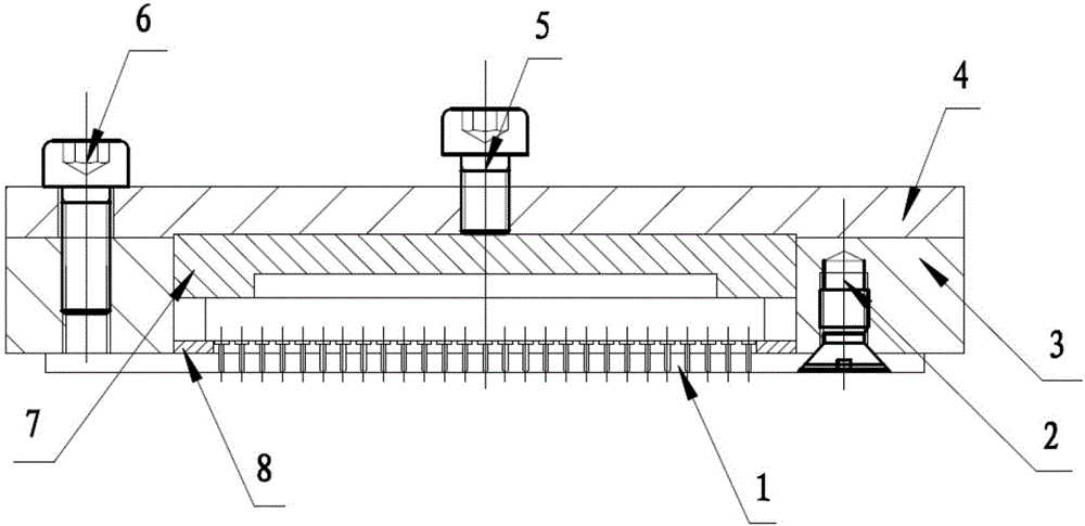
[0050] Using a method of controlling the coplanarity, position and verticality of the device soldering pillars proposed by the present invention, a CCGA717 circuit is processed after the pillars are planted, and the following effects are achieved:

[0051] Welding pillars keep the stencil hole diameter at 0.70mm and thickness at 2.0mm, install the ceramic pillar grid array device on the stencil, and use the welding pillar grinding amount control frame to control the grinding amount, and its thickness is 0.2mm.

[0052] The method and tool of the invention effectively control various indicators of the column planting process of the CCGA717 device, and improve the process quality and consistency. After testing, the coplanarity of the welding post is controlled within 15-40 μm, the position of the welding post is controlled within 60-80 μm, the verticality of the welding post is controlled within 0.3-0.6°, and the qualified rate of post planting reaches 98.8%.


PUM

PropertyMeasurementUnit
Flatnessaaaaaaaaaa

Abstract

The invention discloses a tool and method for controlling coplanarity, position tolerance and perpendicularity of CCGA device welding columns. The method comprises the steps that firstly, welding columns of a ceramic column grid array device are inserted into a welding column retaining plate, and the length, extending out of the welding column retaining plate, of the welding columns is controlled through a welding column grinding amount control frame; parts such as a device fastening pressing block are well installed in sequence, a fastening screw is gently screwed, and close matching between the device and the welding column retaining mesh plate and between the device and the welding column grinding amount control frame is guaranteed; and then the portions, extending out of the welding column retaining mesh plate, of the welding columns are removed through grinding equipment, and polishing is conducted on ground surfaces. In this way, the coplanarity of the welding columns is improved, and meanwhile the position tolerance and perpendicularity of the welding columns are improved by means of the welding column retaining mesh plate. According to the tool and method, the coplanarity of the welding columns can be controlled within 50 micrometers, the position tolerance of the welding columns can be controlled within 100 micrometers, the perpendicularity of the welding columns can be controlled within one degree, and the effect for controlling the coplanarity, position tolerance and perpendicularity of the welding columns is far superior to that of the same kind of devices without using the method.

Description

technical field [0001] The invention relates to a method for controlling the coplanarity, position and verticality of welding posts of a device, in particular to a ceramic post grid array, and belongs to the field of post planting technology for ceramic post grid array devices. Background technique [0002] With the rapid development of modern integrated circuit technology, the miniaturization, high speed and high reliability of integrated circuits require electronic components to be miniaturized and integrated, and at the same time, new packaging technologies are also emerging and developing. As the main packaging form of large-scale integrated circuits today, ball grid array packaging has been widely used in different fields. As a form of ball grid array packaging, ceramic ball grid array packaging has the advantages of high electrothermal performance, strong air tightness, good moisture resistance and high reliability. The ceramic column grid array package is the develop...

Claims


Application Information

Patent Timeline
IPC IPC(8): B24B37/04B24B37/30
CPCB24B37/042B24B37/30
Inventor 唐超姚全斌王勇练滨浩林鹏荣黄颖卓
Owner BEIJING MXTRONICS CORP
Learn More