Optical fiber type ice binding state sensor

A technology combining status and sensors, applied in de-icing devices, transportation and packaging, aircraft parts, etc., can solve the problem that the icing sensor cannot be used to judge the combination status of the ice layer and the surface of the object, and achieve light weight and simple signal processing , small size effect

Inactive Publication Date: 2017-04-19
HUAZHONG UNIV OF SCI & TECH
View PDF4 Cites 3 Cited by
  • Summary
  • Abstract
  • Description
  • Claims
  • Application Information

AI Technical Summary

Problems solved by technology

[0005] The present invention provides a fiber-optic ice binding state sensor, which solves the problem that the existing icing sensors cannot be used to judge the bin

Method used


Image

  • Optical fiber type ice binding state sensor
  • Optical fiber type ice binding state sensor
  • Optical fiber type ice binding state sensor

Examples


Embodiment 1

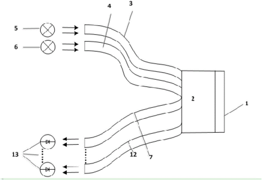
[0027] Embodiment one, as figure 1 As shown, the present embodiment includes 2 transmitting optical fiber bundles and 6 receiving optical fiber bundles. In the figure, the first transmitting optical fiber bundle 3, the second transmitting optical fiber bundle 4, the first receiving optical fiber bundle 7, and the second receiving optical fiber bundle One end of the optical fiber bundle, ..., the sixth receiving optical fiber bundle 12 is bundled into a concentrated optical fiber bundle in the metal casing 2, and its end face constitutes the detection end 1; Both are 2.5mm×3mm;

[0028] Adhesive glue is used between the 2 emitting optical fiber bundles and the 6 receiving optical fiber bundles in the metal shell 2; the other ends of the first emitting optical fiber bundle 3 and the second emitting optical fiber bundle 4 are respectively equipped with The infrared light-emitting diode 5 and the yellow light-emitting diode 6 with a peak wavelength of 590nm, and the other end of ...

Embodiment 2

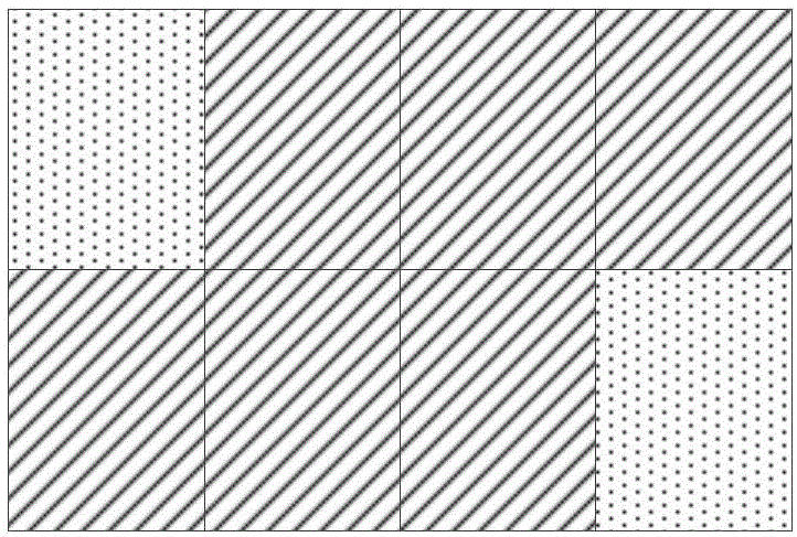
[0030] Embodiment 2. This embodiment includes 3 transmitting fiber bundles and 6 receiving fiber bundles. One end of the 3 transmitting fiber bundles and 6 receiving fiber bundles is bundled into a concentrated fiber bundle in a metal casing, and its end face constitutes a detection end; The cross-section of the optical fiber bundle and the receiving optical fiber bundle is a rectangle with the same area, and the size is 3.33mm×3mm;

[0031] Adhesive glue is used between the 3 emitting optical fiber bundles and the 6 receiving optical fiber bundles in the metal casing; the other ends of the 3 emitting optical fiber bundles are respectively equipped with infrared light-emitting diodes with a peak wavelength of 940nm and red light emitting diodes with a peak wavelength of 700nm. A light-emitting diode and a yellow light-emitting diode with a peak wavelength of 590nm, and a phototransistor is respectively installed at the other end of the 6 receiving fiber bundles.

[0032] In th...

Embodiment 3

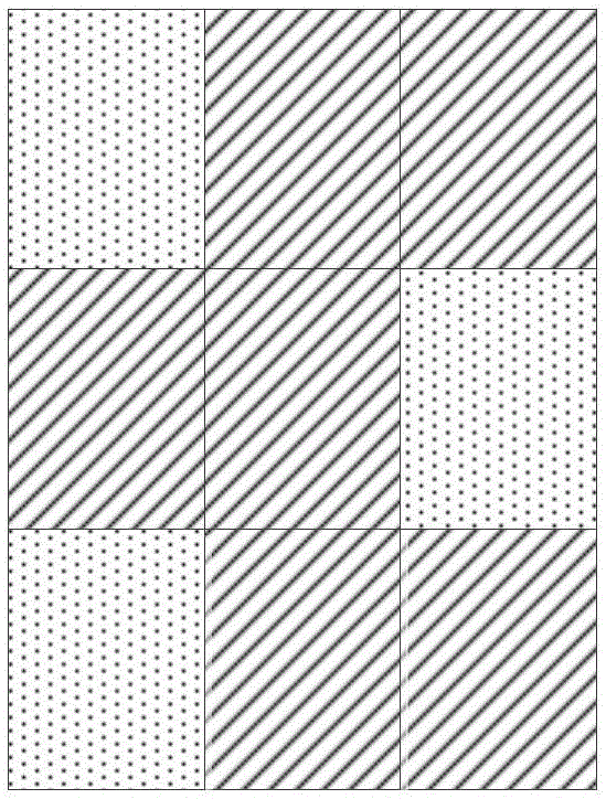
[0033] Embodiment 3. This embodiment includes 2 transmitting fiber bundles and 4 receiving fiber bundles. One end of the 2 transmitting fiber bundles and 4 receiving fiber bundles is bundled into a concentrated fiber bundle in a metal casing, and its end face constitutes a detection end; The cross-sectional area of ​​the optical fiber bundle and the receiving optical fiber bundle is the same;

[0034] Adhesive glue is used between the 2 emitting optical fiber bundles and the 4 receiving optical fiber bundles in the metal shell; the other ends of the 2 emitting optical fiber bundles are respectively equipped with infrared light-emitting diodes with a peak wavelength of 940nm and yellow LEDs with a peak wavelength of 590nm. Light-emitting diodes, the other ends of the 4 receiving optical fiber bundles are respectively equipped with a photoelectric triode.

[0035] In this embodiment, the distribution of the 2 transmitting fiber bundles and the 4 receiving fiber bundles on the en...


PUM


Abstract

The invention relates to an optical fiber type ice binding state sensor, and belongs to the photoelectric sensors. The problem that an existing icing sensor cannot be used for judging the ice layer and material surface binding state is solved, and the optimal shock excitation opportunity is conveniently selected for an electric heating-shock excitation composite type ice removal method. The optical fiber type ice binding state sensor comprises M transmitting optical fiber bundles and N receiving optical fiber bundles, one end of the M transmitting optical fiber bundles and one ends of the N receiving optical fiber bundles are bundled into a metal shell to form concentrated optical fiber bundles, the end face of the optical fiber bundles forms a detecting end, one light source device is installed at the other end of each of the M transmitting optical fiber bundles, and spectrums of the M light source devices are different; and one photoelectric receiving device is installed at the other end of each of the N receiving optical fiber bundles. The optical fiber type ice binding state sensor is small in size, light, capable of achieving multi-point distribution, free of movable accessories, high in reliability and simple in signal treatment, the optical fiber type ice binding state sensor can be used for analyzing influences of phase changes of an ice layer on the object surface on different spectral signals after temperature changes, and the optical fiber type ice binding state sensor is suitable for detecting the binding state of the object icing surface and the ice layer.

Description

technical field [0001] The invention belongs to a photoelectric sensor, in particular to an optical fiber ice binding state sensor, which can qualitatively judge the binding state of an ice layer on the surface of an object, and is applied to the fields of icing detection and anti-icing. Background technique [0002] At present, the electrothermal-excited vibration compound deicing method used for wing deicing firstly reduces the bonding strength between the icing ice layer in the icing area of ​​the wing and the metal skin of the wing by heating after the icing occurs, and then through The exciting vibration destroys the icy layer adhering to the surface of the wing and makes it fall off. In this process, when the vibration starts and how much excitation force is required, effective information is needed as a support. Especially for judging the timing of vibration after heating, it is necessary to detect the combination state of the icy ice layer on the wing surface and th...

Claims


Application Information

Patent Timeline
IPC IPC(8): B64D15/20
CPCB64D15/20
Inventor 叶林葛俊锋桂康陈欣星梁曹佳
Owner HUAZHONG UNIV OF SCI & TECH
Why Eureka
Try Eureka