Supercharge Your Innovation With Domain-Expert AI Agents!

Match gate process engine

An engine, two-stroke technology, applied in the direction of engine components, combustion engines, engine cooling, etc., can solve the problems of large heat load, difficulty in practical use, engine pollution and emission, etc., and achieve the effect of low pollution and simple structure

Active Publication Date: 2017-04-19
SHANGLING HLDG CO LTD
View PDF4 Cites 0 Cited by
  • Summary
  • Abstract
  • Description
  • Claims
  • Application Information

AI Technical Summary

Problems solved by technology

[0002] Using liquefied gas or liquefied oxygen-containing gas (for example, liquefied air) to push the mechanism to do work after the combustion process can effectively solve the problem of engine pollution emissions and efficiency, but the heat load of the mechanism is too large to be practical

Method used


Image

  • Match gate process engine
  • Match gate process engine
  • Match gate process engine

Examples


Embodiment 1

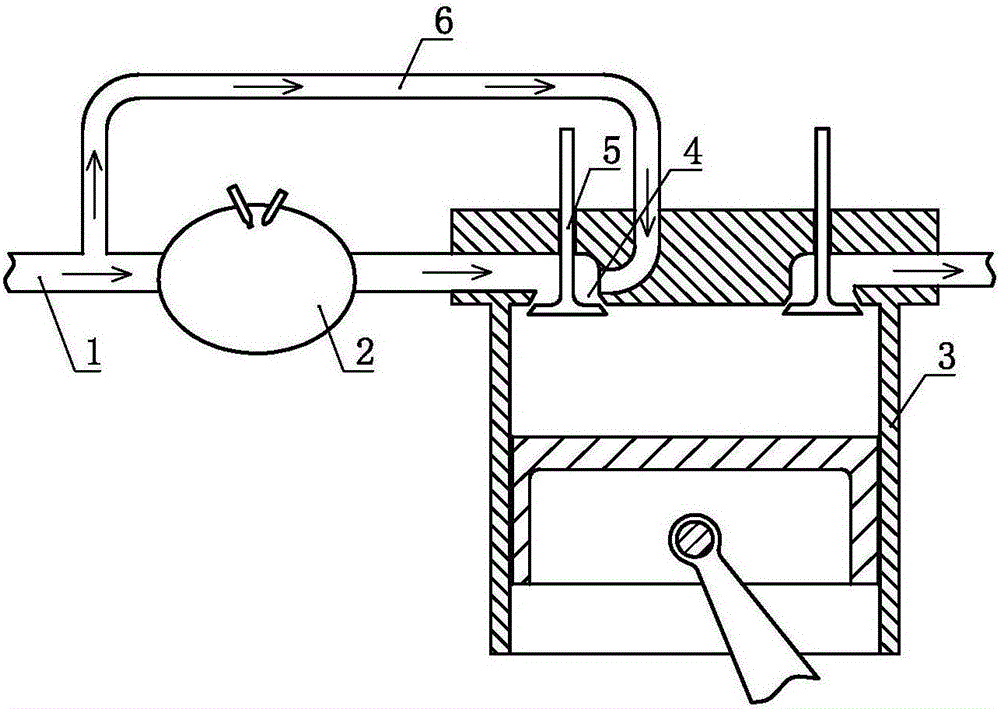
[0043] A homologous process engine such as figure 1 As shown, it includes a working medium passage 1, a combustion chamber 2 and a cylinder-piston mechanism 3, an air charging port 4 is set on the cylinder-piston mechanism 3, an air charging control device 5 is set at the charging port 4, and the working medium passage 1 The combustion chamber 2 is then communicated with the cylinder of the cylinder-piston mechanism 3 through the charging control device 5 and the charging port 4; And the charging port 4 communicates with the cylinder of the cylinder-piston mechanism 3 .

Embodiment 2

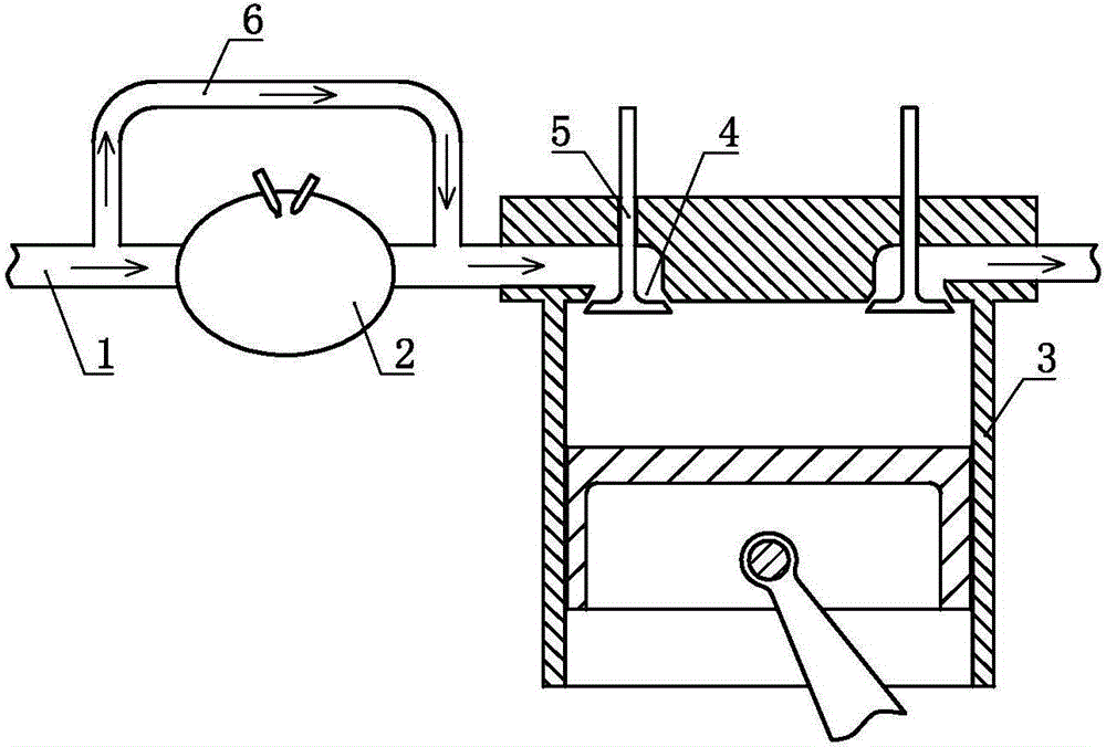
[0045] A homologous process engine such as figure 2 As shown, the difference from Embodiment 1 is that the working medium channel 1 communicates with the fluid channel between the combustion chamber 2 and the gas charging port 4 via a bypass channel 6 .

[0046] As a changeable implementation mode, both Embodiment 1 and Embodiment 2 of the present invention can further selectively choose to make the cylinder-piston mechanism 3 according to the combustion chamber inflation expansion power stroke-exhaust stroke-bypass channel inflation expansion power stroke- The four-stroke working mode of the exhaust stroke works, or the cylinder-piston mechanism 3 is inflated and expanded in accordance with the two-stroke thermal process of the N combustion chambers, and the power stroke-exhaust stroke is then performed in M ​​bypass channels. In the composite working mode of the two-stroke cold process of the gas stroke, the M and the N are both non-zero integers.

[0047] As a convertible e...

Embodiment 3

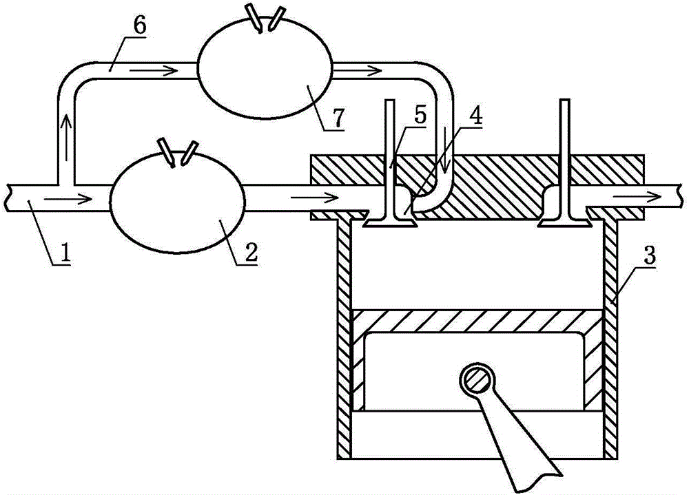
[0049] A homologous process engine such as image 3 As shown, on the basis of Embodiment 1, an auxiliary combustion chamber 7 is further provided on the bypass channel 6 .

[0050] As a changeable embodiment, the embodiment 2 of the present invention and its changeable form and the changeable form of embodiment 1 can further provide an auxiliary combustion chamber 7 on the bypass channel 6 .

[0051] As an alternative embodiment, Embodiment 3 of the present invention and its alternative implementations can further selectively choose to make the combustion chamber 2 and the auxiliary combustion chamber 7 combust alternately or make the combustion chamber 2 and the auxiliary combustion chamber 7 One of the auxiliary combustion chambers 7 is set as a continuous combustion chamber.


PUM


Abstract

The invention discloses a match gate process engine. The match gate process engine includes working medium channels, a combustion chamber, and an air cylinder piston mechanism; air inflation openings are formed in the air cylinder piston mechanism; air inflation control devices are arranged on the air inflation openings; the working medium channels communicate with an air cylinder of the air cylinder piston mechanism via the combustion chamber, the air inflation control devices and the air inflation openings; and the working medium channels communicate with the air cylinder of the air cylinder piston mechanism via bypass channels, the air inflation control devices and the air inflation openings, or the working medium channels communicate with fluid channels between the combustion chamber and the air inflation openings via the bypass channels. The match gate process engine is simple in structure, is less in pollution, is high in efficiency, and can effectively improve the practicability of engines using gas-liquefied products or gas-liquefied products containing oxygen.

Description

technical field [0001] The invention relates to the field of thermal energy and power, in particular to an engine of the same process. Background technique [0002] Using liquefied gas or liquefied oxygen-containing gas (for example, liquefied air) to push the mechanism to do work after the combustion process can effectively solve the pollution emission and efficiency problems of the engine, but the thermal load of the mechanism is too large to be practical. Therefore need to invent a kind of new engine. Contents of the invention [0003] In order to solve the above problems, the technical scheme proposed by the present invention is as follows: [0004] A common process engine, comprising a working medium channel, a combustion chamber and a cylinder-piston mechanism, an air charging port is arranged on the cylinder-piston mechanism, an air charging control device is arranged at the air charging port, and the working medium channel passes through the combustion chamber Th...

Claims


Application Information

Patent Timeline
IPC IPC(8): F02G3/02F01N5/04
CPCF01N5/04F02G3/02F02G2256/50F02G2270/55Y02T10/12
Inventor 靳北彪
Owner SHANGLING HLDG CO LTD
Features
  • R&D
  • Intellectual Property
  • Life Sciences
  • Materials
  • Tech Scout
  • Unparalleled Data Quality
  • Higher Quality Content
  • 60% Fewer Hallucinations
Learn More