Air source heat pump defrosting and deashing device and method based on shock wave and heat pipe technologies

A technology of air source heat pump and ash cleaning device, applied in the direction of cleaning heat transfer device, heat pump, high-efficiency regulation technology, etc., can solve the problems of deteriorating heat transfer effect of heat exchanger, increasing surface heat transfer resistance, increasing air flow resistance, etc. , to achieve the effect of good cleaning, maintenance, and rapid dissemination

Active Publication Date: 2017-04-19
HUBEI FENGSHEN CLEAN AIR CONDITIONING EQUIP ENG
View PDF8 Cites 3 Cited by
  • Summary
  • Abstract
  • Description
  • Claims
  • Application Information

AI Technical Summary

Problems solved by technology

During the long-term use of the air source heat pump outdoor unit, a large amount of dust will accumulate on the surface of the heat exchanger in summer, which will affect the heat exchange efficiency. In addition, the application of air source heat pump products is also limited by climatic conditions, especially in cold regions and the south In humid areas, when the air source heat pump system is running in winter, when the surface temperature of the outdoor heat exchanger is lower than the dew point temperature of the surrounding air and lower than 0°C, frost will form on the surface of the heat exchanger, and the formation of frost will have a negative impact on the heat pump. The performance of the heat exchanger has adverse effects, such as blocking the passage between the fins, increasing the resistance of air flow; increasing the surface heat transfer resistance, deteriorating the heat transfer effect of the heat exchanger, reducing the heat transfer capacity, and even stopping the heat pump system in severe cases run
[0003] The existing defrosting methods of air source heat pumps usually include: hot gas defrosting method, electric heating defrosting method, hot water defrosting method, etc. Their common feature is that the indoor temperature will drop or stop heating during the defrosting process, which wastes Electric energy, causing the heat pump to operate less efficiently
At present, chemical cleaning is mainly used to remove dust from outdoor heat exchangers. The disadvantage of this method is that it will pollute the water source and air, and cause corrosion and other hazards to the equipment.

Method used


Image

  • Air source heat pump defrosting and deashing device and method based on shock wave and heat pipe technologies
  • Air source heat pump defrosting and deashing device and method based on shock wave and heat pipe technologies
  • Air source heat pump defrosting and deashing device and method based on shock wave and heat pipe technologies

Examples


Embodiment 1

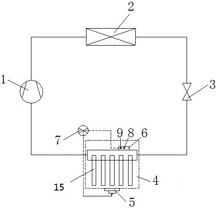
[0035] See attached Figure 1-7

[0036] 1. Parameter setting: separately set the surface temperature of the outdoor heat pipe heat exchanger 4, the thickness of the surface frost layer, the cleaning time, the frost cleaning time, the pressure of the air shock wave generator 5, the inflow and outflow speed of the refrigerant, and the refrigerant cycle The time parameter is set in the controller 7 as a standard comparison parameter.

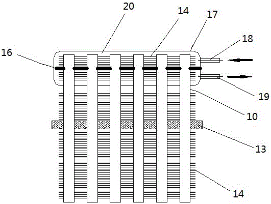
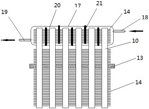
[0037]2. Cooling mode: start the compressor 1, the high-temperature and high-pressure refrigerant gas is discharged through the compressor 1, enters the outdoor heat pipe heat exchanger 4, passes through the heat pipe group 15 installed on the fixed bracket 13, and the header pipe 17 and heat exchange fins The fins 14 exchange heat with the outside air. The refrigerant 20 flows in from the refrigerant inlet pipe 18, and exchanges heat through the heat exchange fins 14 installed on the heat pipe 10 in the header pipe 17 and separated by the inter...

Embodiment 2

[0040] See attached Figure 1-7

[0041] 1. Parameter setting: separately set the surface temperature of the outdoor heat pipe heat exchanger 4, the thickness of the surface frost layer, the cleaning time, the frost cleaning time, the pressure of the air shock wave generator 5, the inflow and outflow speed of the refrigerant, and the refrigerant cycle The time parameter is set in the controller 7 as a standard comparison parameter.

[0042] 2. Heating mode: start the compressor 1, the high-temperature and high-pressure refrigerant 20 gas is discharged through the compressor 1, enters the indoor heat exchanger 2, condenses into a low-temperature and high-pressure liquid, and is throttled by the throttling device 3 before entering the outdoor The heat pipe heat exchanger 4 exchanges heat with the outdoor air through the heat pipe group 15 installed on the fixed bracket 13 , as well as the header pipe 17 and the heat exchange fins 14 . For the inside of the heat pipe, the liqui...


PUM


Abstract

The invention provides an air source heat pump defrosting and deashing device and method based on shock wave and heat pipe technologies. A heat pipe set is arranged in an outdoor heat pipe heat exchanger, an inductor and an air shock wave generator are arranged on the outdoor heat pipe heat exchanger, and the air shock wave generator and the inductor are connected with a controller through USB cables correspondingly. A steam channel is arranged in a heat pipe of the heat pipe set, a liquid absorbing pipe core is arranged on the inner side of a pipe wall, and a fixed support and heat exchanging fins are arranged outside the pipe wall; one end of the heat pipe set communicates into a combined collection pipe, and an intermediate bulkhead or a baffle plate is arranged on the heat pipe set. The method comprises the following steps that (1), parameters are set; (2), a cooling mode is conducted; and (3), a heating mode is conducted. According to the air source heat pump defrosting and deashing device and method based on the shock wave and heat pipe technologies, traditional chemical modes of manual cleansing and defrosting through heating are replaced with a shock wave mode, pollution cannot be generated on a water source and air, and the phenomena that the indoor temperature is lowered, or heating is stopped, and electric energy is wasted caused by defrosting, so that operating efficiency of a heat pump is lowered are avoided; and operational cost is low, the service life is long, operation is easy, control, overhaul and maintenance are convenient, and safety and reliability are achieved.

Description

technical field [0001] The invention relates to the field of shock waves and air source heat pumps, in particular to an air source heat pump defrosting and dust removal device and method based on shock wave and heat pipe technology. Background technique [0002] At present, the air source heat pump system has already entered thousands of households due to its advantages of energy saving, environmental protection, intelligent control, year-round heating and cooling supply, and convenient installation, far exceeding the application of solar energy and geothermal energy and other technologies. During the long-term use of the air source heat pump outdoor unit, a large amount of dust will accumulate on the surface of the heat exchanger in summer, which will affect the heat exchange efficiency. In addition, the application of air source heat pump products is also limited by climatic conditions, especially in cold regions and the south In humid areas, when the air source heat pump ...

Claims


Application Information

Patent Timeline
Patent Type & Authority Applications(China)
IPC IPC(8): F25B47/02F25B30/06F25B41/06F28G13/00F25B41/37
CPCF25B30/06F25B47/02F28G13/00F25B2347/02F25B41/30Y02B30/70
Inventor 周传辉李庆国鲁芬豹赵亚洲代伯清陈敏郭良斌
Owner HUBEI FENGSHEN CLEAN AIR CONDITIONING EQUIP ENG
Why Eureka
Try Eureka