X-ray grazing-incidence reflecting-mirror effective area calibration method

A technology of effective area and calibration method, which is applied in the field of X-ray optics, can solve problems such as low precision, poor parallelism, and difficulty in obtaining it, and achieve the effects of good collimation, lightened operation burden, and easy implementation

Active Publication Date: 2017-04-19
BEIJING INST OF CONTROL ENG
View PDF5 Cites 0 Cited by
  • Summary
  • Abstract
  • Description
  • Claims
  • Application Information

AI Technical Summary

Problems solved by technology

[0005] The technical problem solved by the present invention is: to overcome the deficiencies of the prior art, the present invention provides a method for calibrating the effective area of ​​an X-ray grazing incidence mirror, which limits the diameter of the X-ray beam through an adjustable aperture stop and achieves high collimation The X-ray calibration beam solves the problem that the traditional high-collimation X-ray calibration beam is difficult to obtain; by setting a two-dimensional translation stage, the technical effect of narrow beam scanning to calibrate the effective area of ​​the grazing-incidence mirror is achieved, making up for the calibration accuracy of the traditional method Not high defects; by setting a two-dimensional rotating table, the calibration of the off-axis effective area of ​​the grazing incidence mirror is realized, and the problem of poor parallelism of the traditional calibration method is overcome

Method used


Image

  • X-ray grazing-incidence reflecting-mirror effective area calibration method
  • X-ray grazing-incidence reflecting-mirror effective area calibration method
  • X-ray grazing-incidence reflecting-mirror effective area calibration method

Examples


Embodiment Construction

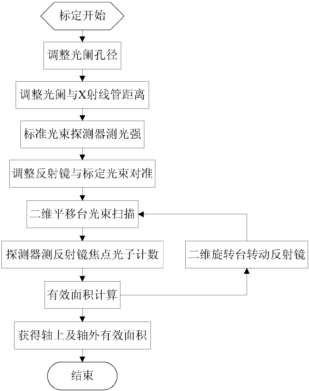
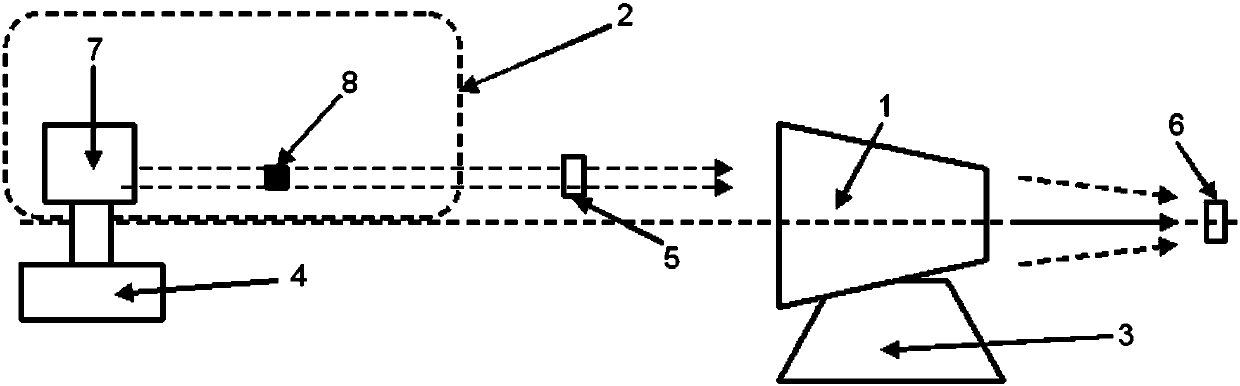
[0034] The present invention will be further described below in conjunction with accompanying drawing description and specific embodiment:

[0035] Such as Figure 1~2 As shown, a method for calibrating the effective area of ​​an X-ray grazing incidence mirror includes an X-ray grazing incidence mirror 1, a narrow beam X-ray source 2, a two-dimensional rotating stage 3, a two-dimensional translation stage 4, a calibration beam detector 5 and mirror focus detector 6; the X-ray grazing incidence mirror 1 is installed on the two-dimensional rotating table 3, and is used to adjust the pitch and deflection biaxial attitude of the X-ray grazing incidence mirror 1, and the narrow beam X-ray source 2 is installed on two On the three-dimensional translation platform 4, it is used to realize the biaxial movement of the narrow-beam X-ray source 2, and then complete the scanning of the grazing incidence mirror 1. The calibration beam detector 5 is installed between the narrow-beam X-ray s...


PUM


Abstract

The invention discloses an X-ray grazing-incidence reflecting-mirror effective area calibration method. The method comprises the following steps of adjusting a diaphragm aperture and a distance between the diaphragm aperture and an X-ray tube, and starting a narrow-beam X-ray source; measuring an X-ray narrow beam intensity; aligning an X-ray grazing-incidence reflecting mirror and the narrow-beam X-ray source; using a two-dimensional translation platform to scan the X-ray grazing-incidence reflecting mirror; measuring a photon number C of a reflecting-mirror focal point; calculating an on-axis effective area of the X-ray grazing-incidence reflecting mirror; and rotating the X-ray grazing-incidence reflecting mirror, repeating the step4 to the step6 and then acquiring an off-axis effective area of the X-ray grazing-incidence reflecting mirror. In the invention, through the adjustable aperture diaphragm, a diameter of a X-ray beam is limited, a high-collimation X-ray calibration beam is realized, and a problem that a traditional high-collimation X-ray calibration beam is difficult to acquire is solved; and through arranging the two-dimensional translation platform, a technical effect that a narrow beam scans and calibrates an effective area of the grazing-incidence reflecting mirror is reached and a defect that calibration accuracy is not high in a traditional method is overcome.

Description

technical field [0001] The invention relates to a method for calibrating the effective area of ​​an X-ray grazing incidence mirror, belonging to the technical field of X-ray optics. Background technique [0002] X-ray grazing incidence mirrors are the core of space-based astronomical observation, space environment monitoring, deep space exploration and navigation tasks, and can increase the collection area of ​​X-ray photons and improve the signal-to-noise ratio of the system. The effective area of ​​the X-ray grazing incidence mirror is the product of the geometrical optics collection area of ​​the system and the reflectivity of the mirror, reflecting the ability of the grazing incidence mirror to collect X-ray photons. Therefore, the calibration of the effective area of ​​the X-ray grazing incidence mirror is a key link in testing and verifying the performance index of the X-ray grazing incidence mirror. [0003] The calibration of the effective area of ​​the X-ray grazin...

Claims


Application Information

Patent Timeline
Patent Type & Authority Applications(China)
IPC IPC(8): G01M11/02
CPCG01M11/02
Inventor 石永强左富昌邓楼楼吕政欣
Owner BEIJING INST OF CONTROL ENG
Why Eureka
Try Eureka