Laser speckle-removing optical path, double-color laser light source, and three-color laser light source

A technology of laser light source and speckle dissipation, applied in optics, optical components, instruments, etc., can solve problems such as speckle effect, achieve the effect of improving uniform distribution and improving light processing efficiency

Active Publication Date: 2017-04-19
QINGDAO HISENSE LASER DISPLAY CO LTD
View PDF9 Cites 6 Cited by
  • Summary
  • Abstract
  • Description
  • Claims
  • Application Information

AI Technical Summary

Problems solved by technology

[0005] The invention provides a laser speckle dissipation optical path, a two-color laser light source, and a three-color laser light source, wh...

Method used


Image

  • Laser speckle-removing optical path, double-color laser light source, and three-color laser light source
  • Laser speckle-removing optical path, double-color laser light source, and three-color laser light source
  • Laser speckle-removing optical path, double-color laser light source, and three-color laser light source

Examples


Embodiment 1

[0047] Embodiment 1 of the present invention provides a laser speckle dissipated optical path, such as Figure 4 As shown, including lasers 1, there can be one or more groups that emit laser light. The lasers can be blue lasers, red lasers or green lasers, and the specific color is not specifically limited.

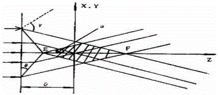
[0048] In the speckle-dissipating light path, a first conical mirror 3 , a diffusion sheet 4 , and a second conical mirror 5 are sequentially arranged along the laser exiting light path. Among them, the first conical mirror 3 is used to homogenize and shape the laser beam, the diffuser 4 is used to diffuse the laser beam homogenized and shaped by the first conical mirror, and the second conical mirror is used to The laser beam is collected and homogenized again.

[0049] Specifically, since the diameter of the laser spot emitted by the laser is about 60 mm, in order to improve the transmission efficiency and shaping efficiency of the laser beam, a beam shrinking componen...

Embodiment 2

[0063] Embodiment 2 of the present invention provides a two-color laser light source, and applies the optical path of laser speckle dissipation described in Embodiment 1 to a two-color laser light source architecture.

[0064] Specifically, such as Figure 7 As shown, the two-color laser light source includes a blue laser 11 and a red laser 12, which respectively emit blue laser and red laser. The blue laser and the red laser can be divided into one or more groups, and the two can be arranged side by side or vertically. The setting will be selected in consideration of the volume of combined light path and the complexity of the heat dissipation structure during specific implementation; and the fluorescent wheel 3 is set in the blue laser exit light path, including the fluorescent area (not shown in the figure) and the transmission area (not shown in the figure), the fluorescent area is provided with green fluorescent powder for being excited by blue laser light to generate gree...

Embodiment 3

[0083] The difference between Embodiment 3 of the present invention and Embodiment 2 is that the fluorescent wheel 3 is a reflective fluorescent wheel, such as Figure 8As shown, the fluorescent light generated by the excitation of the reflective fluorescent wheel is emitted toward the direction opposite to the incident direction of the blue laser light through the reflection of the aluminum substrate, and the light-combining component 4 is placed in front of the fluorescent wheel 3 .

[0084] In order to collimate the transmitted blue laser light and the reflected fluorescent light, collimating lens groups 28 need to be arranged on the front and back of the fluorescent wheel 3 . Wherein the blue laser will also pass through the relay circuit after passing through the collimating lens group 28 on the back side of the fluorescent wheel, including parts such as a relay lens and a plane reflector, such as Figure 9 The optical component 25 shown returns to the light combining com...


PUM


Abstract

The invention discloses a laser speckle-removing optical path which can performs uniform shaping on a Gaussian laser beam by successively arranging a first taper mirror, a diffuser and a second taper mirror in a laser output optical path. In combination with the diffusion effect of the diffuser, the diversity of laser beam divergence angles is formed. The second taper mirror is used for collecting the divergent laser beam so as to ultimately form a light beam uniform distribution way of respective divergence angles near a 0-degree optical axis. The diversity of laser beam divergence angles may reduce the spatial coherence of the laser. Further, the uniform distribution of 0 degree and each divergence angle can prevent a case that the energy of a large-angle divergent beam is over high and thus causes light loss when the divergent beam enters a light collecting part, thereby being beneficial to improvement in the brightness of a laser light source. The technical scheme can take account of the laser speckle removing and the brightness enhancement of the laser light source. The present invention is applied to the technical field of laser display.

Description

technical field [0001] The invention relates to the technical field of laser display, in particular to a laser speckle light path and two-color and three-color laser light sources. Background technique [0002] Laser is a light source with high brightness, strong directionality, and monochromatic coherent light beam. Due to its many advantages, it has been gradually used as a light source in the field of projection display technology in recent years. The high coherence of the laser brings about the speckle effect in the laser projection display. The so-called speckle refers to the scattered light when the coherent light source irradiates a rough object. Interference occurs, some parts of the space have interference constructive, and some parts have interference destructive, the final result is granular light and dark spots on the screen, these unfocused spots appear to be in a flickering state to the human eye, for a long time Viewing is prone to dizziness and discomfort, w...

Claims


Application Information

Patent Timeline
IPC IPC(8): G03B21/20G02B27/48
CPCG02B27/48G03B21/20
Inventor 田有良刘显荣李巍
Owner QINGDAO HISENSE LASER DISPLAY CO LTD
Why Eureka
Try Eureka