Steel wire rope-type photovoltaic tracking system

A tracking system and steel wire rope technology, applied in the field of photovoltaic tracking, can solve the problems of difficult transportation and installation of support, difficulty in installing photovoltaic support, and inability to install photovoltaic support, so as to achieve the effect of improving market competitiveness, low production cost and ensuring stability

Inactive Publication Date: 2017-04-19
WUXI KEANERGY PHOTOVOLTAIC EQUIP CO LTD
View PDF0 Cites 0 Cited by
  • Summary
  • Abstract
  • Description
  • Claims
  • Application Information

AI Technical Summary

Problems solved by technology

[0002] The traditional photovoltaic tracking system support is generally installed and fixed by aluminum alloy, carbon steel and stainless steel profiles. The installation and fixation of this support is strictly affected by the site. When the ground of the site is uneven or misplaced, the photovoltaic support cannot be installed and needs to be leveled manually. To

Method used


Image

  • Steel wire rope-type photovoltaic tracking system
  • Steel wire rope-type photovoltaic tracking system
  • Steel wire rope-type photovoltaic tracking system

Examples


Embodiment 1

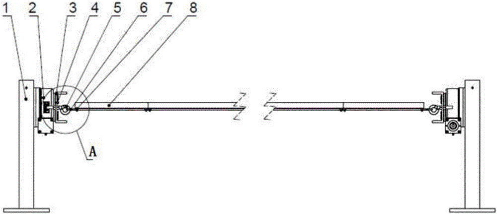
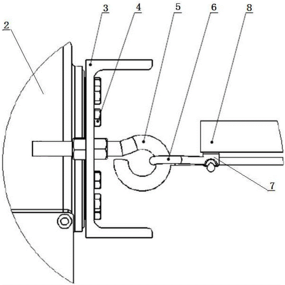
[0048] Such as figure 1 , figure 2 , Figure 6 and Figure 7 As shown, each wire rope 6 includes a wire rope unit 61, and both ends of the wire rope unit 61 are fixedly connected to the horizontal mounting flange 3 through locking rings, and the horizontal mounting flange 3 is fixedly connected to the horizontal mounting flange 3 through bolts 4. On the horizontal rotary drive device 2, the horizontal rotary drive device is fixedly connected to the installation support base 1 by bolts. In this embodiment, the heights of the pair of mounting support bases are consistent. The photovoltaic panel 8 is fixedly connected to the steel wire rope through the wire rope U-shaped clip 7 .

Embodiment 2

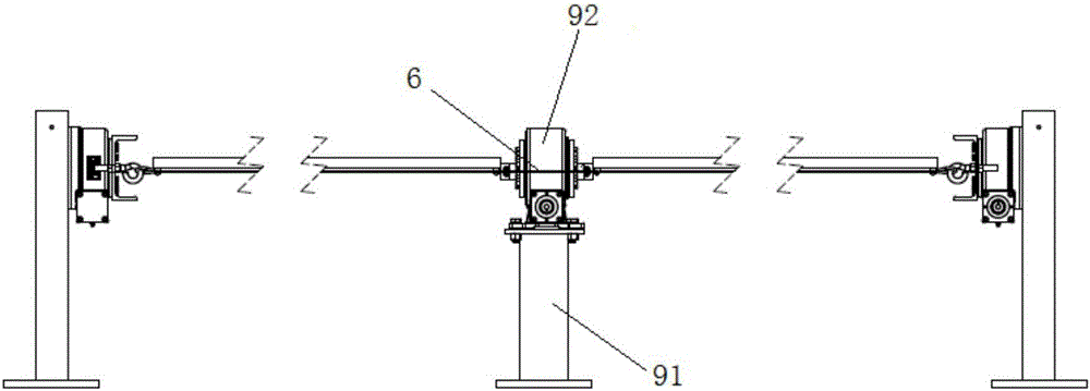
[0050] Such as figure 1 , figure 2 , image 3 , Figure 6 and Figure 7 As shown, each steel wire rope 6 includes a steel wire rope unit 61, and at least one auxiliary installation support seat 91 is provided between a pair of installation support seats, and an auxiliary vertical installation flange 92 is provided on the auxiliary installation support seat. The wire rope passes through the auxiliary vertical mounting flange, and both ends of the wire rope unit 61 are fixedly connected to the horizontal mounting flange 3 through locking rings, and the horizontal mounting flange 3 is fixedly connected to the horizontal mounting flange 3 through bolts 4. On the type rotary drive device 2, the horizontal rotary drive device is fixedly connected to the installation support base 1 by bolts. In this embodiment, the heights of the pair of mounting support bases are consistent. The photovoltaic panel 8 is fixedly connected to the steel wire rope through the wire rope U-shaped cli...

Embodiment 3

[0052] Such as figure 1 , figure 2 , Figure 4 and Figure 6 and Figure 7 As shown, each wire rope 6 includes two wire rope units 61, and the wire rope units are connected by a connector. The connector includes an auxiliary fixing bracket 91, and the top of the auxiliary fixing bracket is provided with an auxiliary rotary drive device 92, which is used for auxiliary rotary drive. There are fixers 95 on both sides of the device 94, and the fixers 95 are fixedly connected to the end of the wire rope unit. The other end of the wire rope unit 61 is fixedly connected to the horizontal installation flange 3 through a locking ring, and the horizontal installation flange 3 passes through Bolts 4 are fixedly connected to the horizontal rotary drive device 2, and the horizontal rotary drive device is fixedly connected to the installation support base 1 by bolts. The photovoltaic panel 8 is fixedly connected to the steel wire rope through the wire rope U-shaped clip 7 .


PUM


Abstract

A steel wire rope-type photovoltaic tracking system disclosed by the present invention comprises a pair of installation supporting seats and a plurality of steel wire ropes, the installation supporting seats are both equipped with horizontal revolution driving devices, the two ends of the steel wire ropes are connected with the horizontal revolution driving devices at the two ends separately, and the steel wire ropes are fixedly connected with the photovoltaic panels. By utilizing the steel wire ropes to substitute for the section bars in the prior art, the photovoltaic panels are installed, the limit of the physiognomy to the installation is solved, at the same time, the production of the steel wire ropes is lower in production cost and higher in production efficiency relative to the production of the section bars, thereby achieving the purposes of reducing the installation difficulty, the work pressure of workers and the production cost and improving the production efficiency and the market competitiveness.

Description

technical field [0001] The invention relates to the field of photovoltaic tracking, in particular to a steel wire rope photovoltaic tracking system. Background technique [0002] The traditional photovoltaic tracking system support is generally installed and fixed by aluminum alloy, carbon steel and stainless steel profiles. The installation and fixation of this support is strictly affected by the site. When the ground of the site is uneven or misplaced, the photovoltaic support cannot be installed and needs to be leveled manually. To be honest, if it is in a mountainous and hilly area, the transportation and installation of this bracket can be said to be difficult. This makes it difficult to install the photovoltaic support, which is time-consuming and labor-intensive. In addition, the production cost of this profile is high, the efficiency is low, and it is not conducive to fierce market competition! Contents of the invention [0003] In order to solve the above techni...

Claims


Application Information

Patent Timeline
IPC IPC(8): H02S20/32F24J2/38F24S50/20
CPCF24S50/20H02S20/32Y02E10/47Y02E10/50
Inventor 王文斌
Owner WUXI KEANERGY PHOTOVOLTAIC EQUIP CO LTD
Why Eureka
Try Eureka