Lathe tool carrier structure for special machine tool

A special machine tool and turning tool technology, applied in the direction of tool clamps, etc., can solve the problems of low safety factor, inconvenient installation and disassembly, large space occupation, etc., and achieve the effect of long service life, good locking effect, and saving lubricating oil.

Inactive Publication Date: 2017-04-26
乐建军
View PDF0 Cites 0 Cited by
  • Summary
  • Abstract
  • Description
  • Claims
  • Application Information

AI Technical Summary

Problems solved by technology

[0002] At present, large-scale mechanical equipment often suffers from irregular deformation or wear during operation, such as plane deformation of the base, wear of the outer circle of the rotating part, etc., or the stress during the manufacturing process is not completely released, and the aging effect is not complete. In place, when transported to the site for installation, the machine will be deformed with the

Method used


Image

  • Lathe tool carrier structure for special machine tool

Examples


Example Embodiment

[0011] Example 1

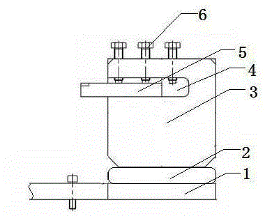
[0012] This embodiment provides a special machine tool turning tool holder structure, which is characterized in that: the special machine tool turning tool holder structure includes a turning tool assembly mounting plate (1), a rotating disk (2), and a tool holder (3). ), turning tool slot (4), turning tool (5), locking bolt (6);

[0013] Among them: the structure includes the turning tool assembly mounting plate (1), and the tool holder (3) and turning tool (5) installed on the turning tool assembly mounting plate (1), the tool holder (3) is installed in the circumferential direction On the rotating rotary disc (2), the turning tool (5) is fixed in the tool holder (3) by the locking bolt (6), and the tool holder (3) is provided with a turning tool clamping groove (5) for installing the turning tool (5) 4).

[0014] The rotating disk (2) is externally connected to the power unit.


PUM


Abstract

A lathe tool carrier structure for a special machine tool is characterized by comprising a lathe tool assembly mounting board, a rotary disc, a tool apron, a lathe tool clamping groove, a lathe tool and lock plungers. The lathe tool carrier structure comprises the lathe tool assembly mounting board, as well as the tool apron and the lathe tool which are mounted on the lathe tool assembly mounting board, wherein the tool apron is mounted on the rotary disc which rotates in the circumferential direction; the rotary disc is externally connected to a power device; the lathe tool is fixed in the tool apron through the lock plungers; and the lathe tool clamping groove allowing the lathe tool to be mounted therein is formed in the tool apron. The lathe tool carrier structure has the following advantages: the structure is simple, the design is reasonable, the locking effect is good, parts have low probability of looseness, are prevented from rigid impact and are long in service life and a lubricant is saved.

Description

technical field [0001] The invention belongs to the field of machining, and in particular provides a special lathe turning tool holder structure. Background technique [0002] At present, large-scale mechanical equipment often suffers from irregular deformation or wear during operation, such as plane deformation of the base, wear of the outer circle of the rotating part, etc., or the stress during the manufacturing process is not completely released, and the aging effect is not complete. In place, when transported to the site for installation, the machine will be deformed with the release of stress. These irregular deformation or wear will lead to abnormal phenomena such as vibration and noise during the operation of the equipment, which will pose a threat to the safe and stable operation of the equipment. The currently used repair device machine tool holder has a complex structure, takes up a lot of space, is inconvenient to install and disassemble, is easy to loosen, and ...

Claims


Application Information

Patent Timeline
IPC IPC(8): B23B29/04
CPCB23B29/04
Inventor 乐建军
Owner 乐建军
Why Eureka
Try Eureka