
Unmanned aerial vehicle

A technology for drones and cameras, applied in the field of drones, can solve the problems of inconvenience to carry, the large size of the drone body, and the weight of the body, so as to ensure the clarity of shooting, the structure is beautiful, and the structure is reasonable. beautiful effect

Inactive Publication Date: 2017-04-26
江苏云端智能科技有限公司
View PDF10 Cites 12 Cited by
  • Summary
  • Abstract
  • Description
  • Claims
  • Application Information

AI Technical Summary

Problems solved by technology

[0003] 1) At present, most of the four-axis and six-axis aircraft are driven by electricity, and the materials used are mostly plastic fiberglass boards, etc., resulting in the drone body being too large and heavy;
[0004] 2) The structure of the gimbal and fuselage carried by most UAVs is complex, which cannot fully achieve 360° shooting without dead angles, and even part of the angle is blocked by the fixed landing gear, and there is no camera protection device for emergency landing;
[0005] 3) The drone itself has the problem of large jitter and strong vibration during flight. In order to ensure the quality of aerial photography and protect the aerial photography equipment, it is necessary to use a self-stabilizing gimbal to cooperate with the aerial photography equipment;
[0006] 4) Most drones equipped with cameras cannot focus manually, and the captured images cannot be fully zoomed according to our requirements, and cannot provide satisfactory monitoring images;
[0007] 5) The flight height of UAVs on the market is mostly measured according to atmospheric pressure. Weather factors have a great influence, and errors are prone to occur. They rarely carry obstacle avoidance devices, and their safety needs to be improved.
[0008] Most of the drones in the existing market are involved in aerial photography, plant protection, and surveying and mapping, which cannot meet the application requirements well
As a result, every time it is used, the cruise capability is insufficient, the operation is cumbersome, and the cost increases. It is not convenient for long-term power line inspection, and it is not easy to carry

Method used


Image

  • Unmanned aerial vehicle
  • Unmanned aerial vehicle
  • Unmanned aerial vehicle

Examples


Embodiment Construction

[0033] The present invention will be described in detail below in conjunction with the accompanying drawings and specific embodiments. However, it should not be understood that the scope of the above subject matter of the present invention is limited to the following embodiments, and all technologies realized based on the content of the present invention belong to the scope of the present invention.

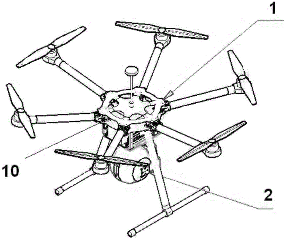
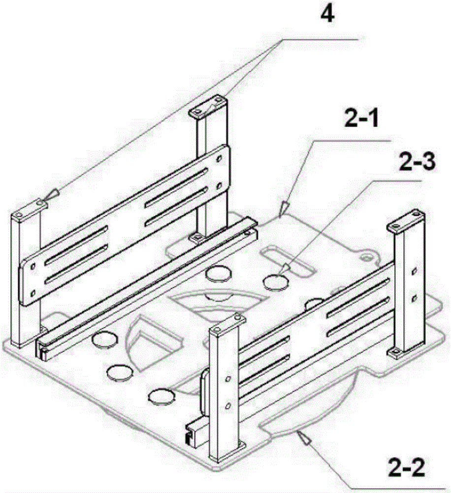
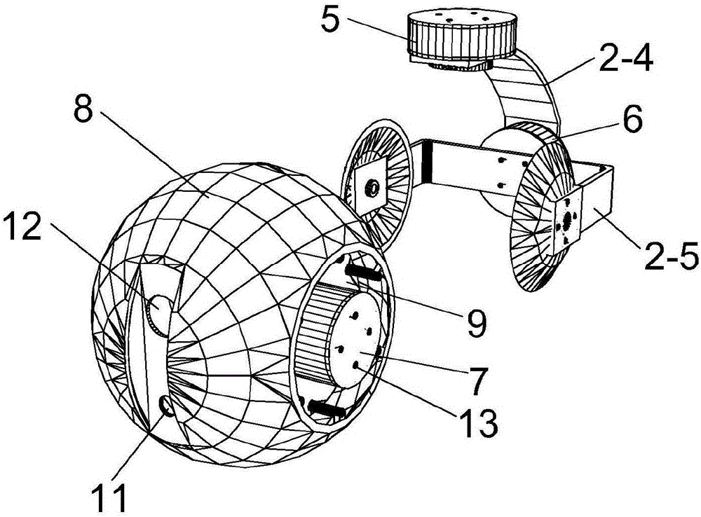
[0034] A kind of unmanned aerial vehicle, comprises unmanned aerial vehicle 1, cloud platform 2 and shooting equipment 3, described cloud platform bottom installs shooting equipment 3, and described cloud platform comprises cloud platform upper plate 2-1, cloud platform shock-absorbing ball 2 -3 and the lower plate of the cloud platform 2-2, the damping ball 2-3 of the cloud platform is connected with the upper plate 2-1 of the cloud platform and the lower plate 2-2 of the cloud platform respectively, and the lower plate of the cloud platform 2-2 Connect the rotating motor 5. Th...


PUM


Abstract

The invention relates to an unmanned aerial vehicle, comprising an unmanned aerial vehicle aircraft, a cradle head and a shooting device, wherein the shooting device is installed at the lower part of the cradle head, the cradle head comprises an upper cradle head plate, a cradle head damping ball and a lower cradle head plate, the cradle head damping ball is connected with the upper cradle head plate and the lower cradle head plate respectively, and the lower cradle head plate is connected with a rotary motor. The used unmanned aerial vehicle can better meet requirements of power line inspection and is compatible with multi-functional devices to meet requirements of long-line power line inspection, self-stabilizing multi-angle zooming shot and self protection.

Description

technical field [0001] The invention relates to the field of unmanned aerial vehicles, in particular to a wireless remote control, control and mechanical design of an electric line patrol unmanned aerial vehicle. Background technique [0002] Unmanned aircraft, referred to as "UAV", is an unmanned aircraft controlled by radio remote control equipment and its own program control device. UAV has the characteristics of small size, light weight, low cost, flexible operation, and high safety. It is widely used in aerial photography, detection, search and rescue, resource exploration and other fields. It is technically feasible to use drones to inspect power lines, and it is of practical significance to promote the work of drones to patrol power lines. UAV power line inspection comprehensively checks the various equipment conditions of lines and towers at a relatively fast speed. At the same time, the precision instruments carried can detect deep-seated line faults and hidden fau...

Claims


Application Information

Patent Timeline
IPC IPC(8): B64D47/08B64C27/08B64C1/00G05D1/04G05D1/08B64C25/10F16F15/04
CPCG05D1/042G05D1/0808F16F15/04B64C1/00B64C25/10B64C27/08B64D47/08B64C2001/0054B64U2101/30B64U2201/10
Inventor 刘东方朱思豪
Owner 江苏云端智能科技有限公司
Learn More