
Device and method for increasing directional solidification and purification yield of polysilicon through reverse centrifuging

A directional solidification, polysilicon technology, applied in chemical instruments and methods, polycrystalline material growth, crystal growth and other directions, can solve problems such as reduced product yield, low impurity removal rate, and easy reverse solidification in impurity areas, to prevent The effect of reverse diffusion and improved utilization

Inactive Publication Date: 2017-04-26
DALIAN UNIV OF TECH
View PDF4 Cites 0 Cited by
  • Summary
  • Abstract
  • Description
  • Claims
  • Application Information

AI Technical Summary

Problems solved by technology

[0004] However, the traditional directional solidification technology solidifies from the bottom to the top, and the removal rate of impurities is low. The final solidified impurity area is prone to reverse solidification, which reduces the yield of the product.

Method used


Image

  • Device and method for increasing directional solidification and purification yield of polysilicon through reverse centrifuging

Examples


Embodiment 1

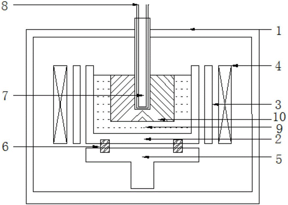
[0028] Such as figure 1 As shown, a reverse centrifugation equipment for improving the directional solidification and purification yield of polysilicon includes a furnace body 1, a silicon material container 2 located in the furnace body 1, and the side wall of the silicon material container 2 is provided with the An annular heating element 3 fixedly connected to the furnace body 1, an annular heating element 4 fixedly connected to the furnace body 1 is arranged on the outside of the annular heating element 3, a rotating tray 5 is arranged at the lower end of the silicon material container 2, and the The rotating tray 5 is fixedly connected to the lower end of the silicon material container 2 through a connecting bolt 6, and the axis of the silicon material container 2 is provided with a water cooling column 7 that can move up and down along the axis of the silicon material container 2. The column 7 is provided with a circulation channel 8 .

[0029] The material of the water...

Embodiment 2

[0034] A method for improving polysilicon directional solidification purification yield by reverse centrifugation using the equipment described in embodiment 1, has the following steps:

[0035] S1. Place the silicon material in the graphite crucible, vacuumize the furnace body 1 to 0.1-3Pa and then pour in flowing argon gas, so that the pressure in the furnace body 1 is 60000-120000Pa, and the ring induction coil is Heating the annular heating element 3 to 1550°C at a heating rate of 10°C / min and keeping it warm for 0.5-1h to obtain a completely melted silicon melt 9;

[0036] S2. After pouring cooling water into the circulating channel 8, insert the water cooling column 7 into the silicon melt 9 obtained in step S1;

[0037] S3. When the polysilicon 10 starts to solidify along the water-cooled column 7, pull the water-cooled column 7 at a speed of 0.07mm / min-0.8mm / min, and at the same time, the graphite crucible follows the rotating tray 5 at a speed of 1- 500r / min speed ro...


PUM


Abstract

The invention discloses a device and method for increasing the directional solidification and purification yield of polysilicon through reverse centrifuging. The device comprises a furnace body and a silicon material container located in the furnace body; the outer side of the side wall of the silicon material container is provided with an annular heat generating body fixedly connected with the furnace body; an annular heating body fixedly connected with the furnace body is arranged on the outer side of the annular heat generating body; a rotating tray is arranged at the lower end of the silicon material container and is fixedly connected with the lower end of the silicon material container through a connecting bolt; the position of the axis of the silicon material container is provided with a water cooling column capable of moving up and down along the axis of the silicon material container; and a circulating flow channel is arranged in the water cooling column. The reverse solidification manner is adopted for the device, under the condition of the gravity effect, impurity diffusion is guaranteed, meanwhile, the centrifugal force guarantees that the thickness of a solid and liquid interface diffusion layer is lowered, and the fractional condensation effect of the device is improved.

Description

technical field [0001] The invention relates to a device and method for reverse centrifugation to improve the yield of directional solidification and purification of polysilicon. Background technique [0002] Directional solidification purification is the main technology to remove metal impurities in polysilicon, and it is widely used in the process of polysilicon ingot casting and metallurgical purification. [0003] Directional solidification purification utilizes the segregation behavior of impurities at the solid-liquid interface: during the directional solidification process, due to the different solubility of impurity elements in the solid and liquid phases, the solute redistribution occurs at the solid-liquid interface of the silicon melt , the degree of redistribution is determined by the segregation coefficient and the solidification rate. The segregation coefficient k0<<1 of metal impurities will continuously enrich in liquid silicon, the impurity content in...

Claims


Application Information

Patent Timeline
IPC IPC(8): C30B29/06C30B28/06
CPCC30B29/06C30B28/06
Inventor 谭毅任世强庄辛鹏李鹏廷姜大川李佳艳
Owner DALIAN UNIV OF TECH
Learn More