Concrete beam composite sidewalk

A technology of concrete beams and composite materials, applied in bridge materials, bridges, bridge parts, etc., can solve the problems of easy peeling of protective layers, increase labor costs, reduce bridge bearing capacity, etc., and achieve low construction equipment and labor costs. Low labor intensity and the effect of reducing the second-phase dead load

Inactive Publication Date: 2017-04-26
RAILWAY ENG RES INST CHINA ACADEMY OF RAILWAY SCI +5
View PDF9 Cites 7 Cited by
  • Summary
  • Abstract
  • Description
  • Claims
  • Application Information

AI Technical Summary

Problems solved by technology

The existing sidewalks have the following disadvantages: (1) The structural quality of the existing railway and highway reinforced concrete, prestressed concrete T-beams, and slab beam sidewalks is too large, which increases the second-stage dead load of the bridge and reduces the bearing capacity of the bridge; (2) ) The steel structure used in the existing sidewalk is easy to corrode and needs to be painted regularly, and the protective layer of the reinforced concrete structure of the existing sidewalk is easy to peel off, expose the ribs, or even break, requiring regular maintenance and replacement, that is to say, its durability is not good; (3 ) The number of existing sidewalk components is large, the site installation workload is large, the construction period is long, and the labor cost is increased; (4) The existing sidewalk walking board is directly placed on the support, which is easily overturned by strong wind; (5) The current Some sidewalks are not made by factories, so the quality is difficult to guarantee

Method used


Image

  • Concrete beam composite sidewalk
  • Concrete beam composite sidewalk
  • Concrete beam composite sidewalk

Examples


Embodiment Construction

[0046] In order to make the object, technical solution and advantages of the present invention clearer, the present invention will be further described in detail below in conjunction with the accompanying drawings and embodiments. It should be understood that the specific embodiments described here are only used to explain the present invention, not to limit the present invention.

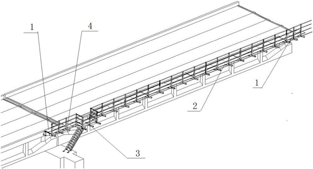
[0047] Such asfigure 1 As shown, a concrete beam composite sidewalk includes standard modules 2 and beam end modules 1, the beam end modules 1 are located at both ends of the concrete beam, and several standard modules 2 are arranged between the beam end modules 1 at both ends. The expansion joints of the concrete beam composite sidewalk are transitioned through the expansion module 4. The expansion module 4 is located between two adjacent concrete beams. One end of the expansion module is placed on the walking board of the beam end module without fixing it. The fasteners are fixed on the walking b...


PUM


Abstract

The invention relates to a concrete beam composite sidewalk which is a novel sidewalk with reinforced concrete and pre-stressed concrete T-shaped beams and plate-type beams for the railway and road. The invention especially relates to a concrete beam sidewalk which adopts the main components made from fiber reinforced composites and fully utilizes the advantages of all the components of the composite material. The concrete beam composite sidewalk comprises standard modules and beam end modules, wherein the beam end modules are located at the two ends of a concrete beam; a plurality of standard modules are arranged between the beam end modules at the two ends; the concrete beam composite sidewalk further comprises a beam end refuge platform module; the beam end refuge platform module instead of one beam end module is arranged at one end of the concrete beam. The concrete beam composite sidewalk can reduce the second phase dead load of the bridge, can increase the bearing capacity of the bridge and can reduce the maintenance cost of the deck ancillary facilities.

Description

technical field [0001] The invention relates to a concrete beam composite sidewalk. Background technique [0002] The sidewalks of reinforced concrete or prestressed concrete T-beams and slab beams are installed on both sides of the bridge, and are mainly used for the safe passage of maintenance personnel and passages in emergency situations. In addition, they are also supporting structures for power and signal cables. One of the most important ancillary facilities. Among them, the T-shaped beam refers to the beam with a T-shaped cross-section, the protruding part on both sides is called the flange, and the middle part is called the beam rib (or web). [0003] The sidewalk mainly bears the vertical load, and at the same time, it is required not to participate in the work of the main body of the bridge. The vertical load of various working conditions is transmitted to the sidewalk support through the walking board, or directly acts on the sidewalk support, and then is transm...

Claims


Application Information

Patent Timeline
Patent Type & Authority Applications(China)
IPC IPC(8): E01D19/00E01D19/12E01D101/24
CPCE01D19/00E01D19/12E01D2101/24
Inventor 牛斌曾志斌陈忠海李再轲张松崎赵沭通沙磊张勇范霆张跃进卢瑞林朱波曾挚刘志陈才洋
Owner RAILWAY ENG RES INST CHINA ACADEMY OF RAILWAY SCI
Why Eureka
Try Eureka