

Underground fluid gas extraction device and process
An underground fluid and gas lift technology, applied in water supply installations, drinking water installations, buildings, etc., can solve problems such as difficult processing, strict requirements on well construction size, and complex structure of the gas lift system, so as to improve the applicability, The effect of small diameter of pump body and cost reduction
- Summary
- Abstract
- Description
- Claims
- Application Information
AI Technical Summary
Problems solved by technology
Method used
Image

Examples
Embodiment 1
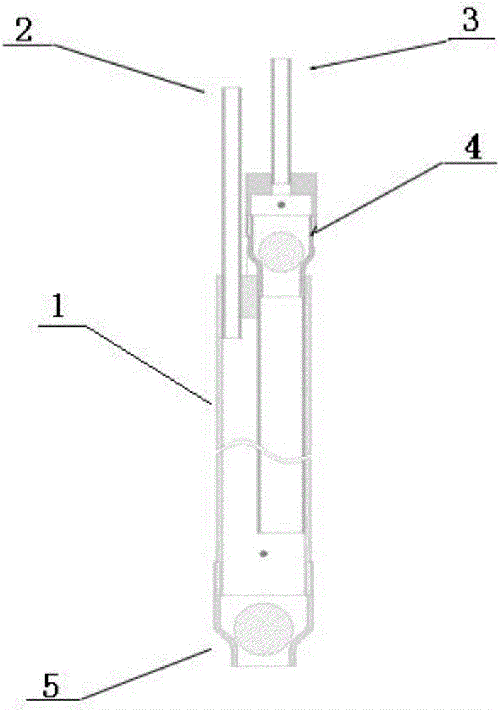
[0040] This embodiment provides an underground fluid gas stripping device, such as figure 1 As shown, it includes a closed pump body, and the upper and lower ends of the pump body are respectively provided with an upper one-way valve for controlling the liquid outlet and a lower one-way valve for controlling the liquid inlet; the side of the pump body is provided with Air intake controlled by valve.
[0041] The pump body is made of SS316 material, and the pump body is a slender cylinder.
[0042] The pump body has a length of 0.5-2m and a diameter of 40-100mm.
[0043] The pressure of the gas passing through the air inlet is 1-4Bar, and the air intake time is 1-30s.
[0044]Close the valve at the upper end of the air inlet, stop the air intake, open the one-way valve at the lower end, close the one-way valve at the upper end, and the underground fluid enters the pump body for liquid storage, and the liquid storage time is 10-600s.
[0045] The valve at the upper end of the...
Embodiment 2
[0046] Embodiment 2 groundwater extraction process
[0047] The size of the extraction well is 110mm in the present embodiment; the length of the pump body of the underground fluid gas lifting device used is 1.2m, and the diameter is between 50mm;
[0048] Proceed as follows:
[0049] (1) Water storage stage: close the valve at the upper end of the air inlet, stop the air intake, the upper one-way valve is automatically closed, the lower one-way valve is opened by the water pressure, groundwater enters the pump body, and the water storage time is 30s;
[0050] (2) Water lifting stage: Open the valve at the upper end of the air inlet to control the pressure of the injected gas to 3Bar, the gas injection time is 5s, the air is injected into the pump body, and the lower one-way valve is pressed, and the upper one-way valve is opened. , to 0.8m 3 The water extraction rate of / h extracts the groundwater from the outlet hole;
[0051] (3) Exhaust stage: close the valve at the upp...
Embodiment 3
[0053] Embodiment 3 groundwater extraction process
[0054] The size of the extraction well is 200mm in the present embodiment; the length of the pump body of the underground fluid gas lifting device used is 1.8m, and the diameter is between 70mm;
[0055] Proceed as follows:
[0056] (1) Water storage stage: close the valve at the upper end of the air inlet, stop the air intake, the upper one-way valve is automatically closed, the lower one-way valve is opened by the water pressure, groundwater enters the pump body, and the water storage time is 60s;
[0057] (2) Water lifting stage: Open the valve at the upper end of the air inlet to control the pressure of the injected gas to 4Bar, the gas injection time is 10s, the air is injected into the pump body, and the lower one-way valve is pressed, and the upper one-way valve is opened. , to 2m 3 The water extraction rate of / h extracts the groundwater from the outlet hole;
[0058] (3) Exhaust stage: close the valve at the uppe...
PUM
| Property | Measurement | Unit |
|---|---|---|
| Length | aaaaa | aaaaa |
| Diameter | aaaaa | aaaaa |
| Size | aaaaa | aaaaa |
Abstract
Description
Claims
Application Information