Gas heating device

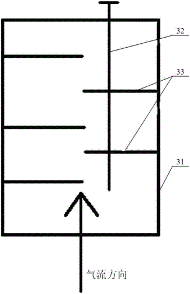
A technology for gas heating devices and heating chambers, which is applied in the direction of electric heating devices, air heaters, fluid heaters, etc., which can solve the problems of large airflow resistance, obvious noise on site, and high-frequency vibration of the partition 33, so as to avoid resonance and noise , not easily deformed, and the effect of improving work efficiency

Inactive Publication Date: 2017-04-26
YANGGU XIANGGUANG COPPER
View PDF5 Cites 6 Cited by
  • Summary
  • Abstract
  • Description
  • Claims
  • Application Information

AI Technical Summary

Problems solved by technology

[0004] like figure 1 As shown, the heating pipe 32 of the existing gas heating device is usually inserted into the equipment body 31 from the top of the body 31 in the vertical direction and penetrates the partition 33. The partition 33 is usually arranged horizontally and is limited by the structure and space at the same time. In the prior art, the partition 33 mostly adopts a thin plate, and the partition 33 adopts a half width and multi-layer arrangement, and the airflow resistance is large, and the partition 33 has high-frequency vibration under the impact of the large air flow, and the noise on site is obvious; in addition, due to the horizontal arrangement of the partition 33 has no effective support, resulting in large deformation of the partition 33 under the action of high-speed airflow and high temperature during the operation of the equipment. Therefore, after the electric heating tube 32 is pulled out during use, it cannot be inserted back into its original position, resulting in the replacement of the electric heating tube 32 every time Or maintenance requires downtime, unable to achieve online replacement or maintenance

Method used


Image

  • Gas heating device
  • Gas heating device
  • Gas heating device

Examples


Embodiment Construction

[0024] The core of the present invention is to provide a gas heating device, the internal components of the gas heating device are reasonably arranged, the working noise is small, and the heating tube can be replaced or repaired online.

[0025] In order to enable those skilled in the art to better understand the solution of the present invention, the present invention will be further described in detail below in conjunction with the accompanying drawings and specific embodiments.

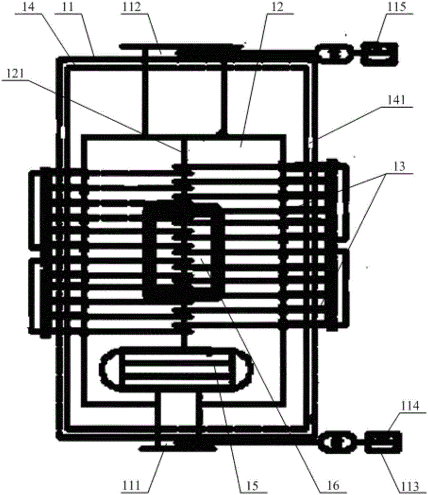
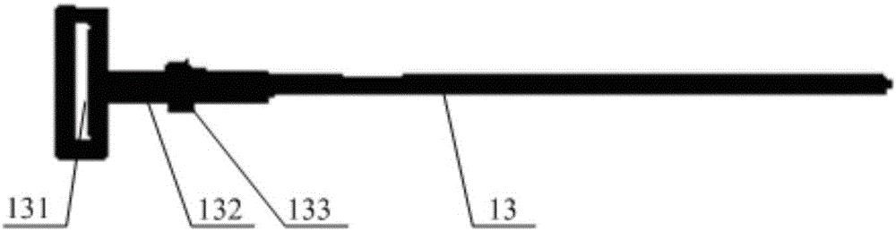
[0026] Please refer to figure 2 and image 3 , figure 2 A structural perspective view of a gas heating device provided by a specific embodiment of the present invention; image 3 for figure 2 Schematic diagram of the structure of the heating tube part.

[0027] In a specific embodiment, the gas heating device provided by the present invention includes an insulated housing 11. A heating chamber 12 is arranged inside the insulated housing 11. The bottom of the insulated housing 11 has an air i...


PUM


Abstract

The invention discloses a gas heating device. The gas heating device comprises an insulation shell. A heating chamber is arranged inside the insulation shell. A gas inlet enabling the heating chamber and an external gas inlet pipe to communicate is formed in the bottom of the insulation shell. A gas outlet enabling the heating chamber and an external gas outlet pipe to communicate is formed in the top of the insulation shell. A partition plate is arranged in the middle of the heating chamber in the vertical direction. A plurality of heating pipes which sequentially penetrate through the side walls of the heating chamber and the partition plates in the horizontal direction are arranged on the lateral portion of the insulation shell, and the heating pipes are sequentially arranged in the vertical direction. Wiring terminals which are connected with an external power distribution cabinet are arranged at the outer ends of the heating pipes. According to the gas heating device, internal assemblies are arranged reasonably, working noise is low, and online replacement or maintenance of the heating pipes can be achieved.

Description

technical field [0001] The invention relates to the technical field of gas heating equipment, in particular to a gas heating device. Background technique [0002] At present, in the existing metal smelting or machining fields, electric heaters are a kind of gas heating equipment commonly used, and with the continuous improvement of people's product process requirements, the performance of gas heating devices is also increasingly concerned by people . [0003] Please refer to figure 1 , figure 1 It is a structural schematic diagram of a gas heating device in the prior art. [0004] Such as figure 1 As shown, the heating pipe 32 of the existing gas heating device is usually inserted into the equipment body 31 from the top of the body 31 in the vertical direction and penetrates the partition 33. The partition 33 is usually arranged horizontally and is limited by the structure and space at the same time. In the prior art, the partition 33 mostly adopts a thin plate, and the...

Claims


Application Information

Patent Timeline
Patent Type & Authority Applications(China)
IPC IPC(8): F24H3/04F24H9/18F24H9/00F24H9/20H05B3/02
CPCF24H3/0405F24H9/0052F24H9/1863F24H9/2071H05B3/023
Inventor 孙伟
Owner YANGGU XIANGGUANG COPPER
Why Eureka
Try Eureka