
Heterodyne Laser Vibration Measurement Method Based on Bandpass Sampling

A technology of band-pass sampling and laser vibration measurement, which is applied in the direction of measuring devices, measuring ultrasonic/sonic/infrasonic waves, instruments, etc., can solve the problems of external analog devices and phase delay, limited vibration measurement accuracy, and large amount of processed data. , to achieve the effects of high vibration signal measurement accuracy, small amount of processed data, and low sampling frequency

Active Publication Date: 2019-10-18
NAT INST OF METROLOGY CHINA +1
View PDF5 Cites 0 Cited by
  • Summary
  • Abstract
  • Description
  • Claims
  • Application Information

AI Technical Summary

Problems solved by technology

[0005] The purpose of the present invention is to provide a band-based vibrometer based on the current heterodyne laser vibrometer method, which has the shortcomings of high sampling frequency and large amount of processed data or the need for external analog devices, phase delay, and limited vibration measurement accuracy. Heterodyne Laser Vibration Measuring Method Through Sampling

Method used


Image

  • Heterodyne Laser Vibration Measurement Method Based on Bandpass Sampling
  • Heterodyne Laser Vibration Measurement Method Based on Bandpass Sampling
  • Heterodyne Laser Vibration Measurement Method Based on Bandpass Sampling

Examples


Embodiment Construction

[0055] In order to solve the problems of the existing heterodyne laser vibration measurement methods requiring high sampling frequency, large amount of collected data and poor real-time performance, or the need for external analog devices, a certain phase delay, and limited measurement accuracy, the present invention provides a The heterodyne laser vibration measurement method based on bandpass sampling will be described in detail below with reference to the accompanying drawings and specific implementation examples.

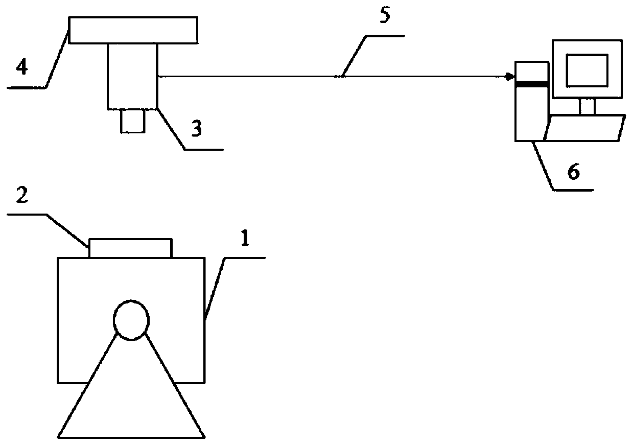
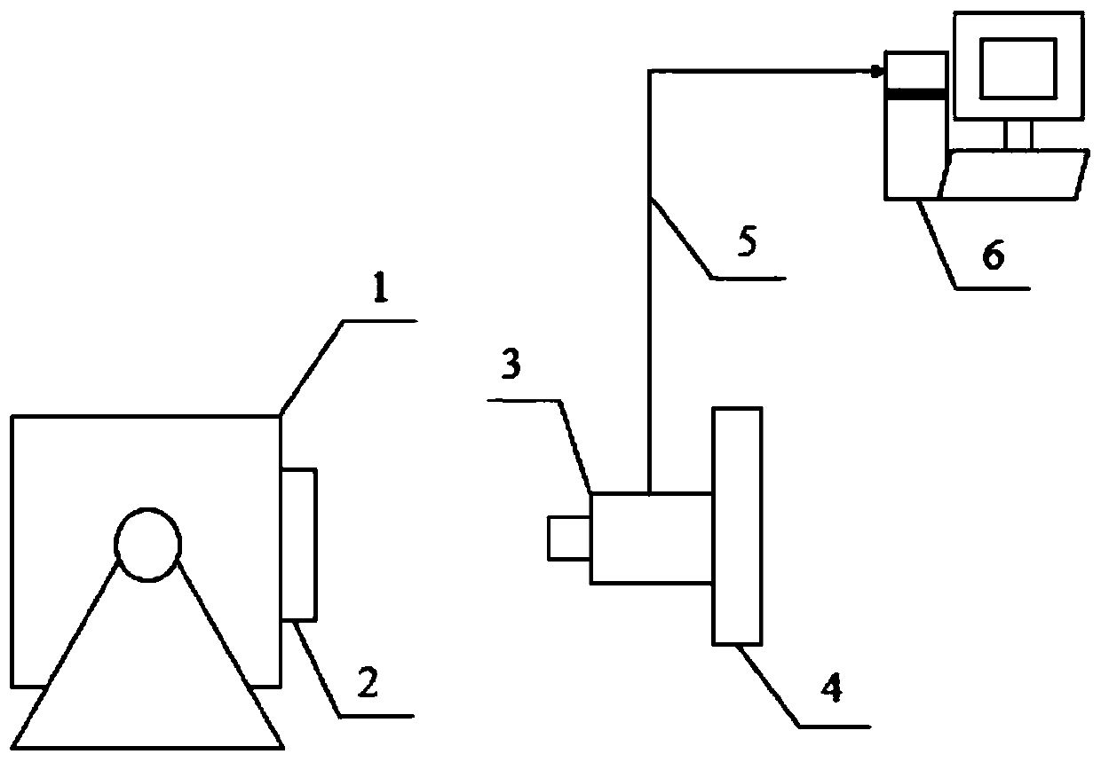
[0056] reference figure 1 versus figure 2 It is a schematic diagram of an example device for implementing the method of the present invention. The device mainly includes: a vibrating table 1, a vibrating table work surface 2, a heterodyne laser interferometer 3, a vibration isolation table 4, a cable 5, and a signal processing and display device 6. The vibration isolation table 4 is used to fix the heterodyne laser interferometer 3 and is perpendicular to the work...


PUM


Abstract

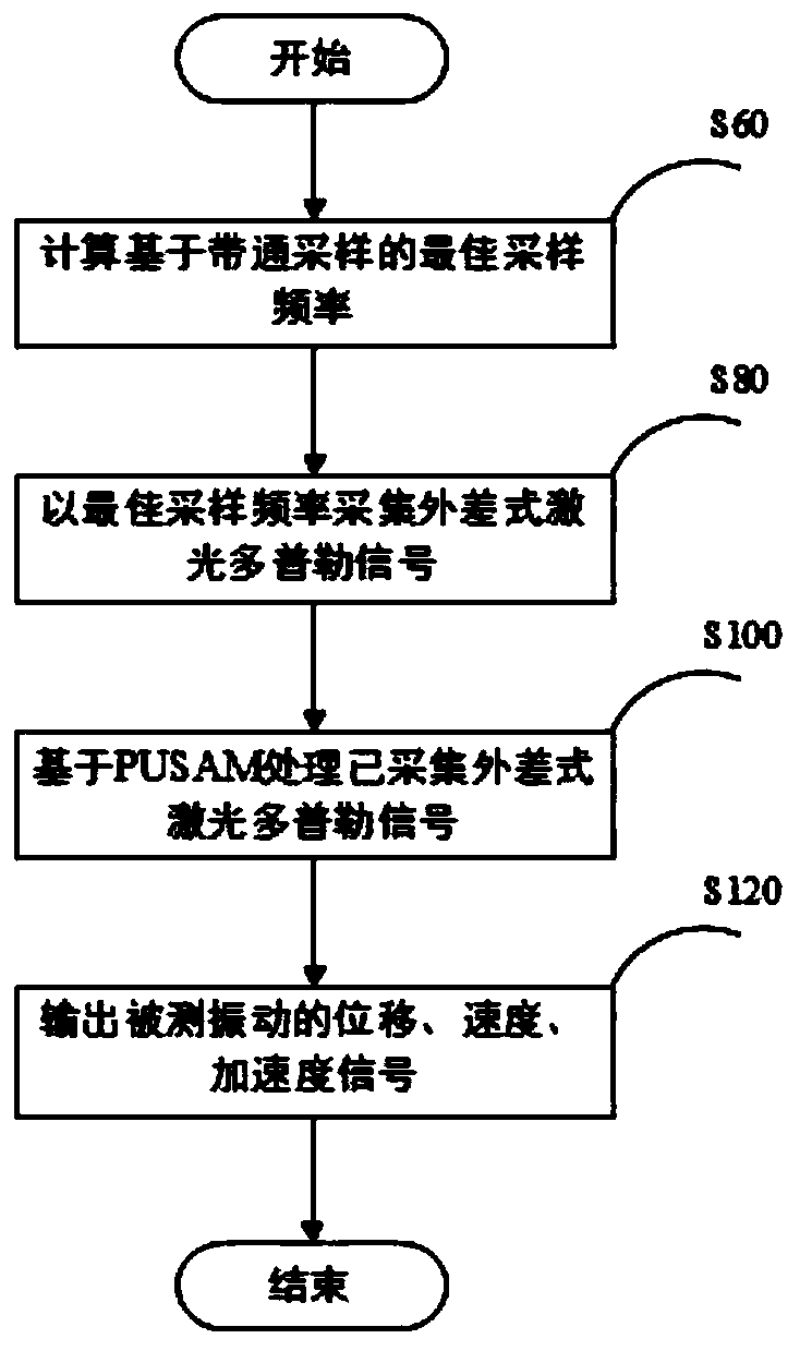
The invention discloses a heterodyne laser vibration measuring method based on band-pass sampling. The effective sampling frequency band corresponding to different integers m for avoiding spectrum aliasing of heterodyne laser Doppler signals after acquisition is determined based on the band-pass sampling theorem. Through a band-pass sampling protection bandwidth, enough engineering allowance is ensured, and spectrum aliasing of actual laser Doppler signals is avoided. An optimal sampling frequency automatic selection method based on band-pass sampling is put forward to determine the optimal sampling frequency of heterodyne laser Doppler signals. Finally, acquired heterodyne laser Doppler signals are demodulated based on a phase unwrapping sinusoidal approximation method (PUSAM). The method has the characteristics of low sampling frequency, a small amount of data acquired, good real-time performance and no phase relay on the premise of guaranteeing high-precision vibration measurement effectively. By using the method, the problem that the traditional heterodyne laser vibration measuring method has the disadvantage of high sampling frequency or phase relay for heterodyne laser vibration measurement is solved effectively.

Description

Technical field [0001] The invention belongs to the field of laser vibration measurement, and is particularly suitable for vibration signal measurement in a heterodyne laser interference absolute method vibration calibration. Background technique [0002] The heterodyne laser vibration measurement method mainly includes the collection of heterodyne laser Doppler signals and the demodulation of the collected laser Doppler signals. The purpose of collection is to ensure that the heterodyne laser can be simulated without spectrum aliasing. The conversion of Doppler signal to digital laser Doppler signal, the purpose of demodulation is to realize the measured vibration measurement through heterodyne laser Doppler signal. For the conventional absolute vibration calibration of heterodyne laser interferometry, the bandwidth of the heterodyne laser Doppler signal is much smaller than the carrier frequency of the heterodyne laser Doppler signal, which is based on the band-pass sampling of...

Claims


Application Information

Patent Timeline
Patent Type & Authority Patents(China)
IPC IPC(8): G01H9/00
Inventor 蔡晨光杨明刘志华王颖
Owner NAT INST OF METROLOGY CHINA
Learn More