
Self-coupled probe mechanism based on parallel passive-type fine adjustment structure

A passive, self-coupling technology, used in material analysis, measurement devices, and instruments using sonic/ultrasonic/infrasonic waves. The effect of eliminating detection blind spots and high work efficiency

Inactive Publication Date: 2017-04-26
CHANGZHOU UNIV
View PDF5 Cites 12 Cited by
  • Summary
  • Abstract
  • Description
  • Claims
  • Application Information

AI Technical Summary

Problems solved by technology

However, due to the shortcomings of the ultrasonic automatic flaw detection equipment independently developed by my country, such as low degree of automation, low detection efficiency, and poor accuracy, most of these problems are caused by ultrasonic probes.
Although the quality of flaw detection can be improved through imported ultrasonic probes, there are problems such as matching between imported probes and domestic flaw detection equipment. In addition, imported probes are expensive, have a long delivery cycle, and cannot be configured in large quantities, and their main technologies are in the hands of foreign suppliers. , in the event of shortages, production stoppages, technical limitations or other factors, it is likely that there will be no probes available, and it is very likely that the flaw detection operation will be stopped. At that time, the safe, normal and continuous operation of the EMU will not be guaranteed.

Method used


Image

  • Self-coupled probe mechanism based on parallel passive-type fine adjustment structure
  • Self-coupled probe mechanism based on parallel passive-type fine adjustment structure
  • Self-coupled probe mechanism based on parallel passive-type fine adjustment structure

Examples


Embodiment Construction

[0013] The present invention will be further described below in conjunction with accompanying drawing. The following examples are only used to illustrate the technical solution of the present invention more clearly, but not to limit the protection scope of the present invention.

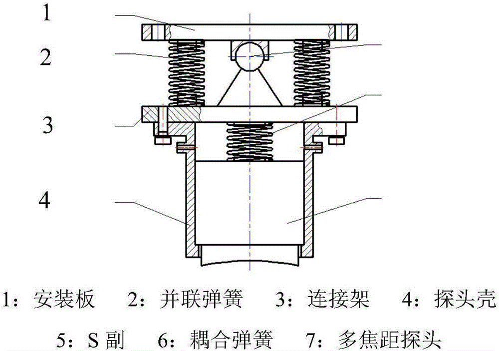
[0014] Such as figure 1 As shown, a self-coupling probe mechanism based on a parallel passive fine-tuning structure, including a mounting plate (1) of a fixed mechanism, a parallel spring (2), a connecting frame (3), a probe shell (4), an S pair (5), Coupling spring (6), multi-focus probe (7); through the mounting plate (1), the entire probe mechanism can be installed on the wheel automatic flaw detection host; the parallel spring (2) and the S pair (5) are located on the mounting plate (1) and Between the connecting brackets (3), the swing position and posture of the probe can be adjusted according to the specific shape change of the wheel tread of the motor vehicle; the terminal on one side of the...


PUM


Abstract

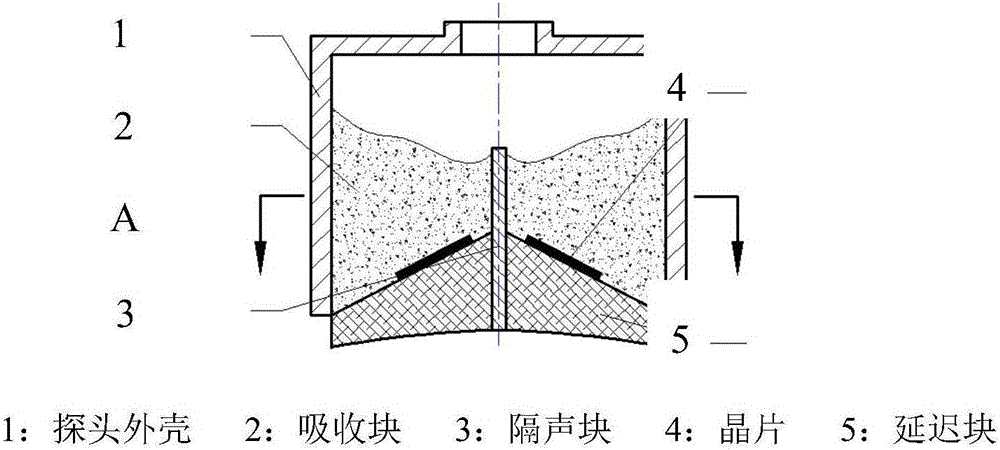
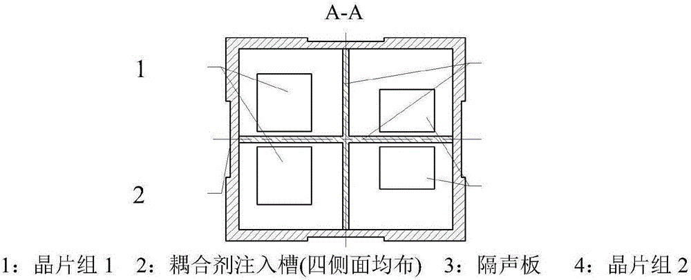
The invention discloses a self-coupled probe mechanism based on parallel passive-type fine adjustment structure, which belongs to the technical field of supersonic wave automatic flaw detection. The self-coupled probe mechanism comprises an installing plate, parallel springs, a connection rack, a probe shell, a S pair, a coupling spring, and a multi-focal probe; the installing plate and a flaw detection host are connected; the parallel spring and the S pair are placed between the installing plate and the connection rack; the connection rack is connected with the probe shell by a screw, and is connected with the installing plate by the S pair, and a set of parallel springs are cooperated; the multi-focal probe with a square cross section is inserted in the square probe shell, the multi-focal probe and the square probe shell enable sliding fit, and the coupling spring is arranged at tail of the probe. While flaw detection is carried out, the probe and a wheel tread are contacted for pressing, movement and swing can be carried out under common effect of the parallel springs, the S pair, and the coupling spring, when the shape of the wheel tread is changed, the probe position and pose is passively adjusted with real time, good coupling can be maximally guaranteed. In addition, an angle-changeable wafer arranged in the probe realize multiple focal length, so that flaw detection on near surface of wheel tread and deeper area can be simultaneously carried out.

Description

technical field [0001] The invention relates to a self-coupling probe mechanism based on a parallel passive fine-tuning structure, belonging to the technical field of non-destructive testing (ultrasonic automatic flaw detection). Background technique [0002] Ultrasonic flaw detection of EMU wheels is an important part of the EMU operation and maintenance system. The ultrasonic probe used in flaw detection is the core component of wheel flaw detection equipment, and its quality and performance are directly related to the accuracy of wheel flaw detection results. The structure of the probe should not only take into account the nature and type of defects that may be produced by the detected object, defect direction, size, etc., but also consider the detection surface shape characteristics of the detected object. The parallel passive fine-tuning self-coupling probe mechanism involved in the present invention is mainly used for the automatic flaw detection of the EMU wheels use...

Claims


Application Information

Patent Timeline
Patent Type & Authority Applications(China)
IPC IPC(8): G01N29/24G01M17/10
CPCG01N29/2437G01M17/10G01N2291/023G01N2291/263G01N2291/2696
Inventor 邓嘉鸣马龙
Owner CHANGZHOU UNIV
Learn More