
A method for judging the switch state and distance position of electrical equipment in a power distribution system

A technology of switch status and power distribution system, applied in the direction of measuring current/voltage, measuring electricity, measuring devices, etc., can solve the problems of large cost and engineering volume, stop detection and calculation, and difficult monitoring of a single device, so as to increase hardware The effect of investment

Active Publication Date: 2019-01-29
SHENZHEN POLYTECHNIC
View PDF7 Cites 0 Cited by
  • Summary
  • Abstract
  • Description
  • Claims
  • Application Information

AI Technical Summary

Problems solved by technology

[0002] At present, the monitoring of online power equipment generally stays in the detection and calculation of the overall energy consumption of a district or a family or a building, and it is difficult to monitor whether a single device is working online in real time
The main reason is that, as far as the current technical level is concerned, the monitoring of each device must be equipped with relevant detection instruments one by one. Such a huge cost and engineering volume is unbearable.

Method used


Image

  • A method for judging the switch state and distance position of electrical equipment in a power distribution system
  • A method for judging the switch state and distance position of electrical equipment in a power distribution system
  • A method for judging the switch state and distance position of electrical equipment in a power distribution system

Examples


Embodiment Construction

[0024] specific implementation plan

[0025] The present invention will be further described in detail below through specific embodiments in conjunction with the accompanying drawings.

[0026] Some of the electrical equipment in the distribution network use three-phase, and some use single-phase. For simplicity of discussion, the specific embodiments of the present invention only consider single-phase equipment, however, the following conclusions and results are also applicable to three-phase situations.

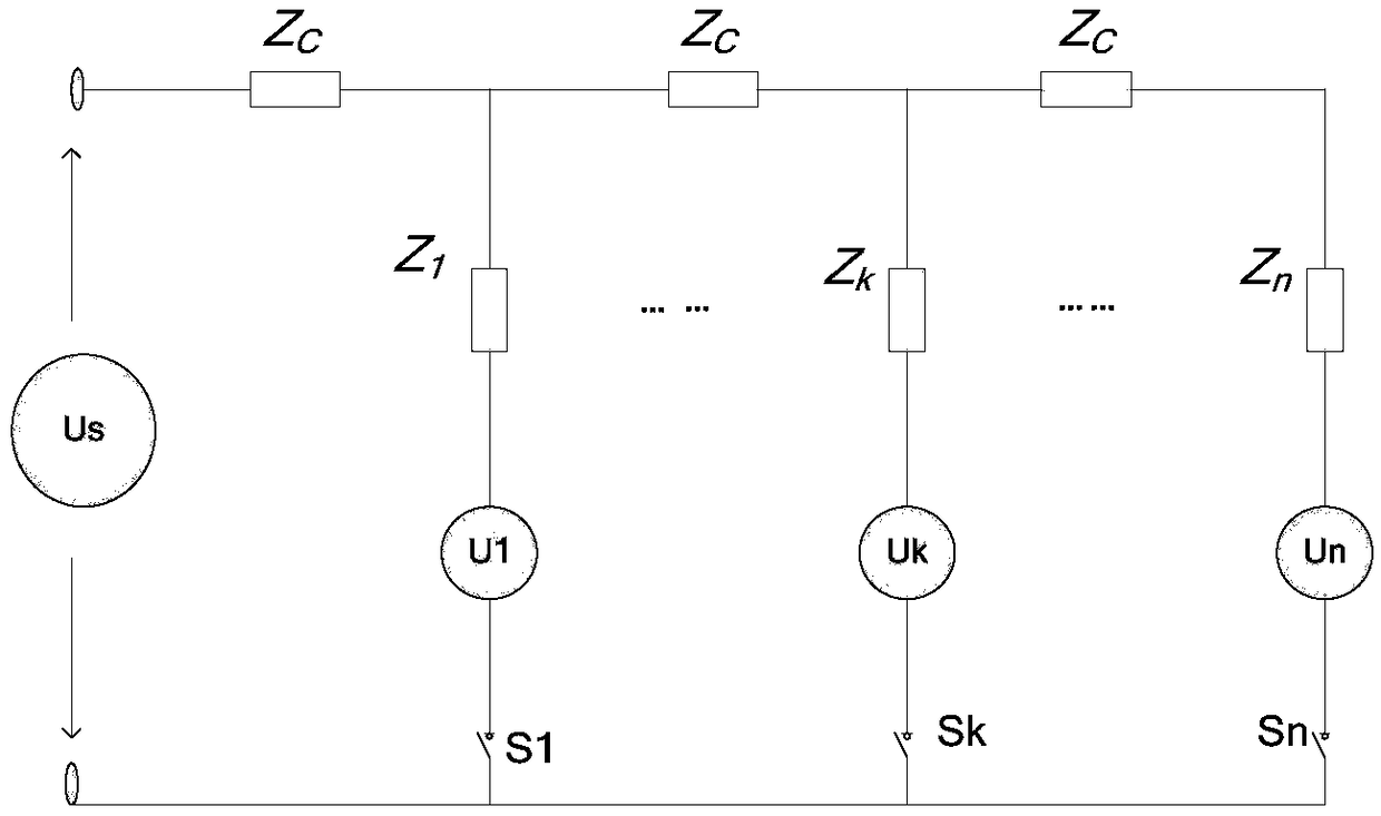
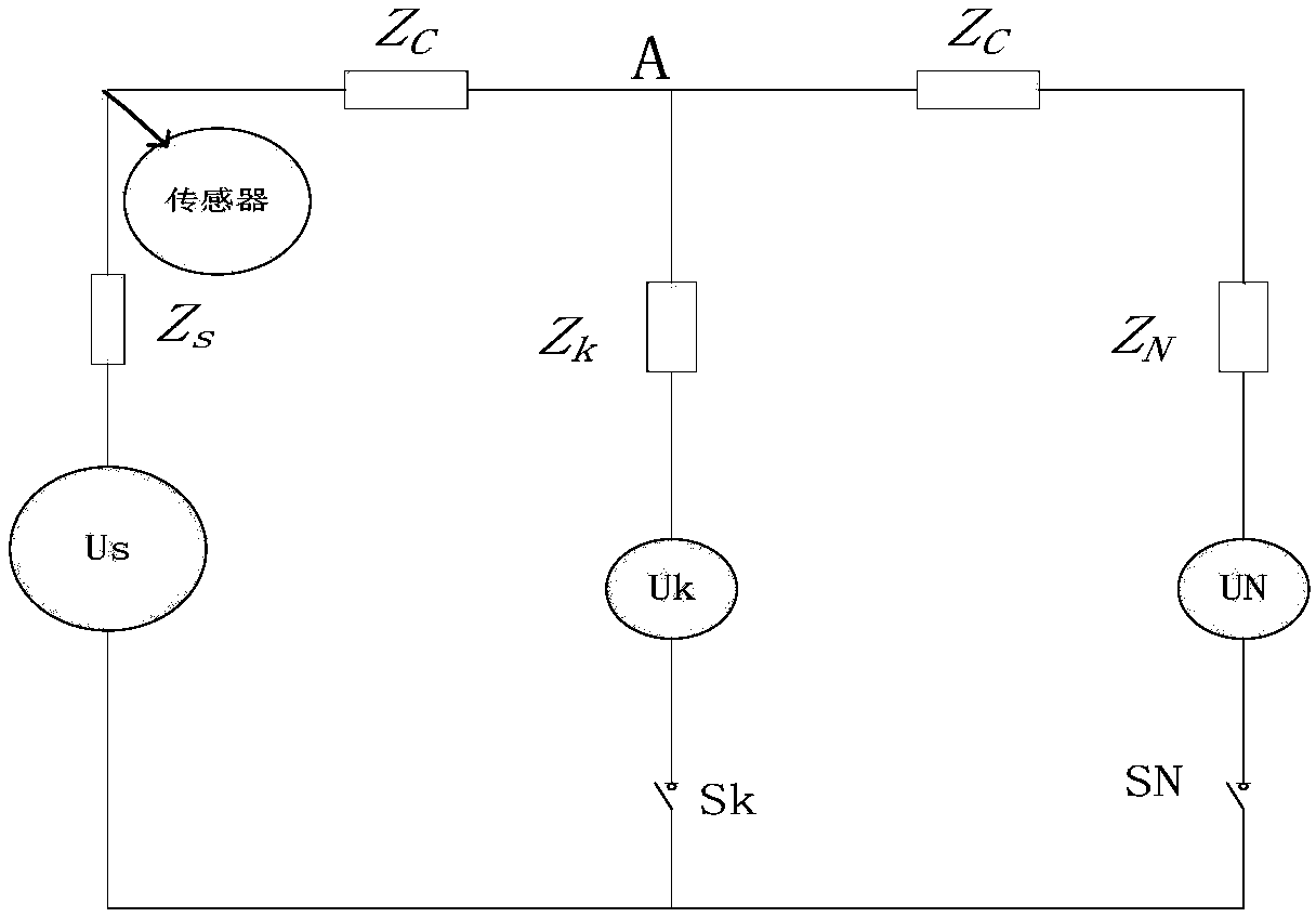
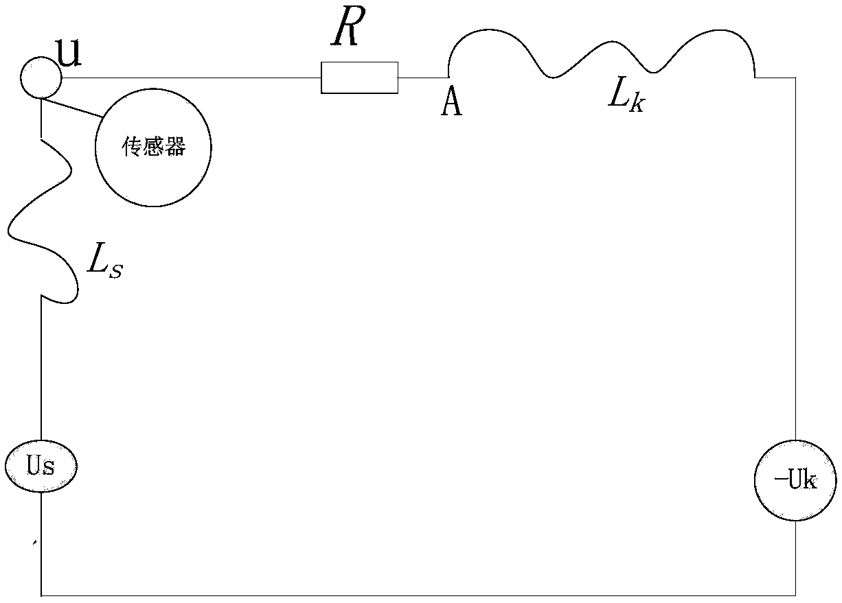
[0027] Without loss of generality and for the sake of simplifying the calculation, assuming that the power supply conductors of the distribution network are lossless and uniform conductors, the network structure of the system powered by electrical equipment in the distribution network can be seen in the appendix figure 1 . Among them, Us is the unidirectional power supply voltage provided by the bus, U1, Uk, and Un are the first electrical equipment load, the kth load, an...


PUM


Abstract

The invention provides a switch state and distance position determining method for electric equipment of a distribution system. Current and voltage sensors are mounted in the input end of a phase line to detect switch signals of electric equipments in different branches of the phase, and the switch signals are analyzed to determine the switch states and distance positions of the electric equipments to monitor the electric equipments; when it is detected that a voltage response is a downwardly attenuated exponential function and a current response equals a sum of a downward constant and a downwardly attenuated exponential function, a switch of the electric equipment is determined to be changed from a connected state to a disconnected state; when it is detected that a voltage response equals a sum of an upward pulse function and an upwardly attenuated exponential function and a current response equals a downwardly attenuated exponential function, a switch of the electric equipment is determined to be changed from the disconnected state to the connected state; and the distance from the electric equipment to the sensor is determined by utilizing different transmission speeds of different frequencies of harmonic waves in a loss power grid transmission line and waveform time difference detected by the sensor.

Description

technical field [0001] The invention relates to the technical field of power grid monitoring, in particular to a method for judging the switch status and distance position of electrical equipment in a power distribution system. Background technique [0002] At present, the monitoring of online power equipment generally stays in the detection and calculation of the overall energy consumption of a district or a family or a building. It is difficult to monitor whether a single device is working online in real time. The main reason is that, as far as the current technical level is concerned, the monitoring of each device basically must be equipped with relevant detection instruments one by one. Such a huge cost and engineering volume are difficult to bear. Contents of the invention [0003] The purpose of the present invention is to overcome the problem of difficult monitoring of online electrical equipment in the prior art, and install current and voltage sensors at the incom...

Claims


Application Information

Patent Timeline
Patent Type & Authority Patents(China)
IPC IPC(8): G01R19/00G01R31/00
CPCG01R19/00G01R31/00
Inventor 王根平
Owner SHENZHEN POLYTECHNIC
Learn More