Non-isolated LED dimming circuit with PWM and DIM dimming

A dimming circuit, non-isolated technology, applied in the field of LED dimming, can solve the problems of complex and incompatible peripheral circuits, and achieve the effect of high chip isolation

Active Publication Date: 2017-04-26
无锡恒芯微科技有限公司
View PDF8 Cites 8 Cited by
  • Summary
  • Abstract
  • Description
  • Claims
  • Application Information

AI Technical Summary

Problems solved by technology

[0007] LED lighting driver chips generally require two dimming methods, PWM dimming and analog dimming, which can be implemented in various w

Method used


Image

  • Non-isolated LED dimming circuit with PWM and DIM dimming
  • Non-isolated LED dimming circuit with PWM and DIM dimming
  • Non-isolated LED dimming circuit with PWM and DIM dimming

Examples


Example Embodiment

[0021] The specific implementation of the present invention will be described in detail below with reference to the accompanying drawings, taking two-way LED and other lighting circuits as an example, without limitation.

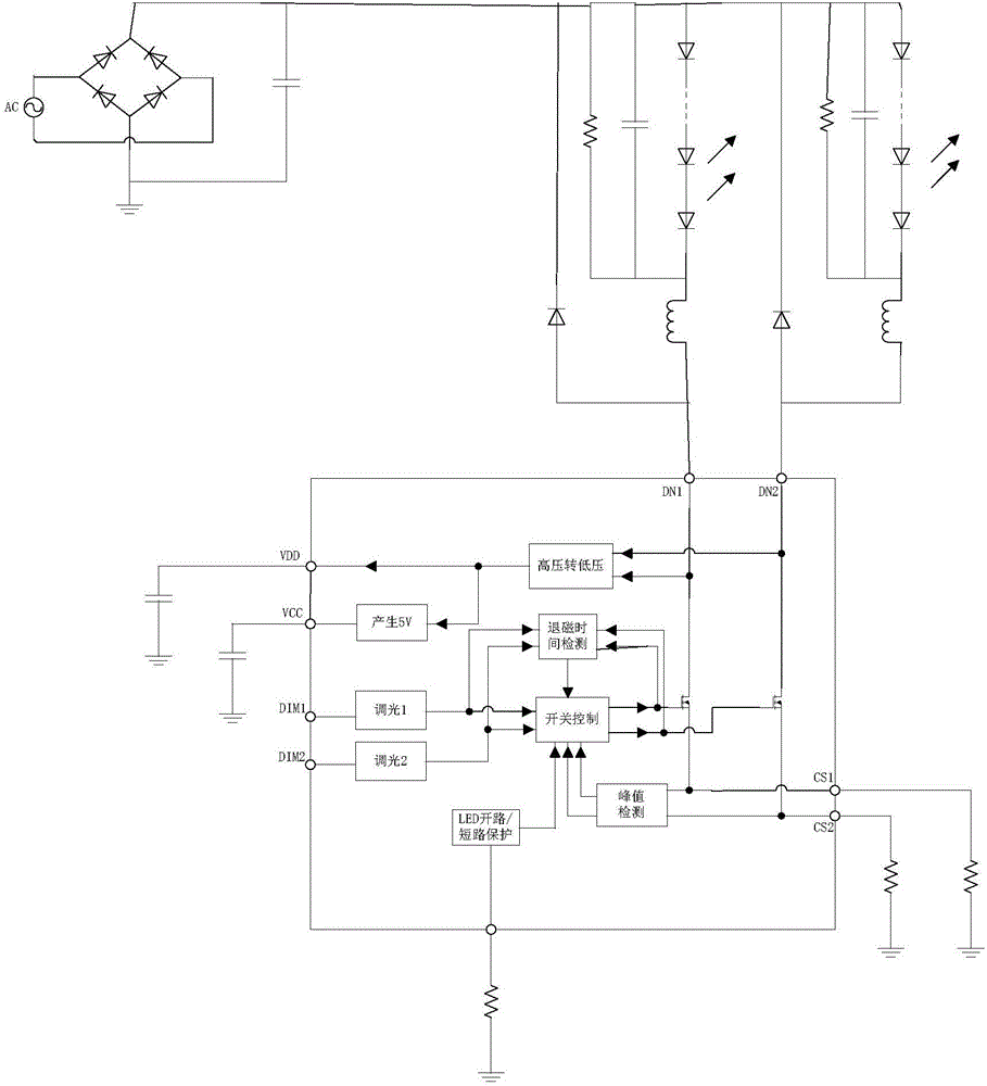
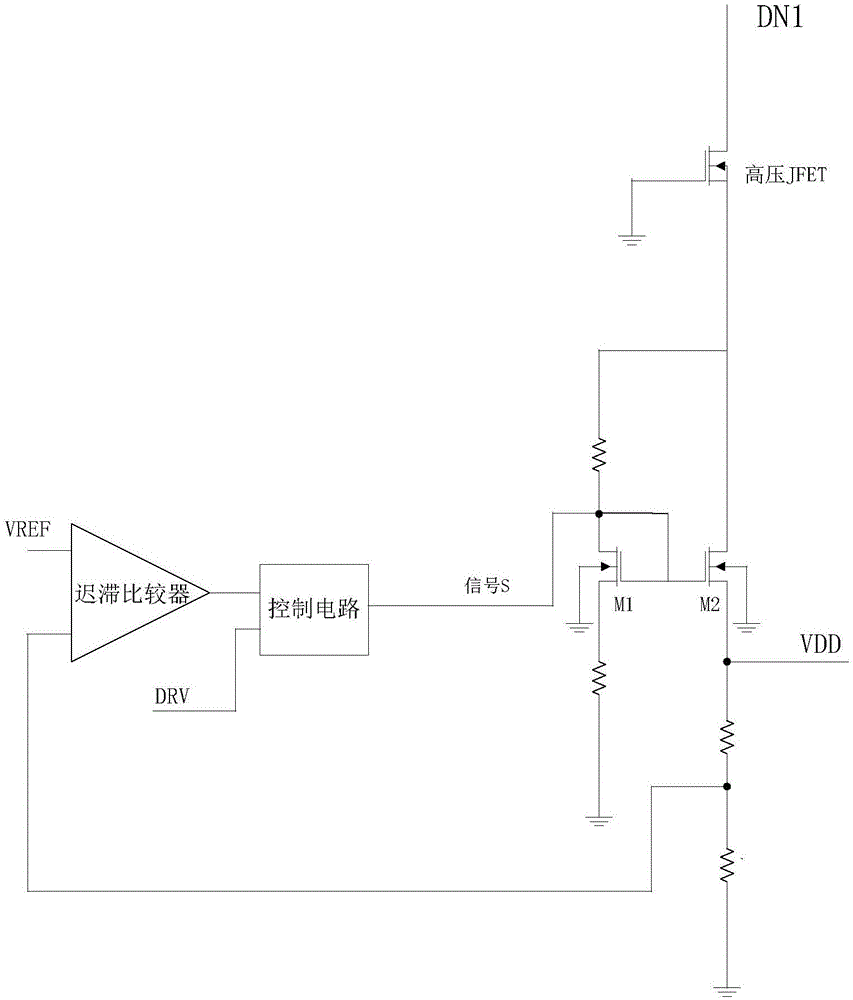
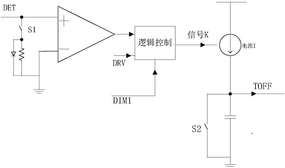
[0022] Such as figure 1 As shown, the non-isolated LED dimming circuit with PWM and DIM dimming of the present invention includes an LED lighting circuit and a dimming circuit; the lighting circuit includes two LED lamps, and each lamp tube is connected in parallel with a capacitor, resistor and inductor at both ends , There is a Schottky tube between the inductor and the LED lamp. The inductance is discharged through the Schottky tube and the LED lamp, and this discharge time is the demagnetization time.

[0023] The dimming circuit includes a high-voltage to low-voltage module, a demagnetization time detection module, a switch control module, a peak detection module, and two dimming signal input terminals; each dimming signal input terminal is compatible with D...


PUM


Abstract

The invention discloses a non-isolated LED dimming circuit with PWM and DIM dimming, relating to the technical field of LED dimming. The circuit comprises an LED lighting circuit and a dimming circuit. The dimming circuit comprises a high voltage to low voltage module, a demagnetization time detection module, a switch control module, a peak detection module and a dimming signal input end. The demagnetization time detection module adjusts the closing time of a high voltage MOS tube according to an input direct current signal, thus a demagnetization time is adjusted. The peak detection module adjusts the peak of inductance discharge in the LED dimming circuit. The switch control module controls the gate of the high voltage MOS tube according to an input PWM signal, the output signal of the demagnetization time detection module and the signal of the peak detection module, thus the current of an LED lamp is adjusted, 5V voltage is outputted, power can be supplied to the MCU and Bluetooth module of a control system and a radar module, an additional power supply is not needed, the chip isolation is high, and two ways of control can be applied independently without affecting each other.

Description

technical field [0001] The invention relates to the technical field of LED dimming, in particular to an LED dimming circuit with PWM and DIM dimming. Background technique [0002] There are two commonly used methods for dimming existing LED lamps: [0003] 1. Linear dimming; [0004] Linear dimming is mainly based on the principle of simple voltage division. Its advantages are simple application and no interference. The disadvantages are inflexibility and low efficiency. At the same time, it may cause chromatographic shift and excessive heat to increase the temperature. [0005] 2. PWM dimming mode [0006] An LED is a diode, which can be switched on and off quickly. Its switching speed can be as high as more than microseconds. It is unmatched by any light-emitting device. Therefore, as long as the power supply is changed to a pulse constant current source, the brightness can be changed by changing the pulse width. [0007] LED lighting driver chips generally require t...

Claims


Application Information

Patent Timeline
IPC IPC(8): H05B33/08H05B44/00
CPCH05B45/00
Inventor 吴建良顾南昌吴洁
Owner 无锡恒芯微科技有限公司
Why Eureka
Try Eureka