Pot handle structure with controller

A technology with controllers and controllers, which is applied in the direction of program control, electrical program control, and collectors in sequence/logic controllers. It can solve the problem of adding control chips, unsatisfactory functions, and lack of intelligent control of other kitchen appliances. problems, to achieve the effect of comfortable use, easy replacement and disassembly, and prevention of heat conduction

Pending Publication Date: 2017-05-10
GUANGDONG MACRO GAS APPLIANCE
View PDF4 Cites 5 Cited by
  • Summary
  • Abstract
  • Description
  • Claims
  • Application Information

AI Technical Summary

Problems solved by technology

[0002] The pot handles in the prior art generally only have a simple function of lifting the pot, and some have a safety control function added to the pot handle, such as the safety control function that cannot be electrically heated when the pot is not covered when the handle of the electric pressure cooker is set. The pot handle is a relatively frequent and convenient operating device that people use in kitchen cookware. No one has tried to improve it, and the existing structure cannot meet the requirements of adding new functions. Therefore, the traditional handle has been used so far. With the function of intelligently controlling other kitchen appliances, the existing structure cannot meet the requirements of adding control chips and circuits inside; and with the popularization of smart furniture, people's demand for smart pots continues to increase, and the existing pot handle structure cannot meet user needs.

Method used


Image

  • Pot handle structure with controller

Examples


Embodiment Construction

[0019] The patent of the present invention will be further described below in conjunction with the drawings and embodiments.

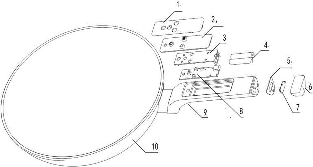
[0020] Such as figure 1 As shown, a pot handle structure with a controller of the present invention includes a pot handle body 9. The pot handle body 9 uses bakelite and nylon plus a fiber body and is connected to the pot 10, and the pot handle body 9 is provided There is a sealable cavity in which the controller 8 and power supply of household appliances (such as hoods, stoves, disinfection cabinets, rice cookers, etc.) with control chips are installed. The power supply adopts the battery 4, and the controller 8 is connected to the power supply. Connect, a short-distance wireless transmitter is installed in the controller.

[0021] The cavity is composed of ABS electrical box, rubber key gasket 5 and other materials.

[0022] The controller 8 is fixed inside the pot handle 9 with screws. The upper part of the controller is a fixing bracket 3, and a rubber ...


PUM


Abstract

The invention discloses a pot handle structure with a controller. The pot handle structure comprises a pot handle body and is characterized in that a cavity capable of being closed is formed in the pot handle body, a domestic electric controller with a control chip and a power supply are installed in the cavity, the controller is electrically connected with the power supply, and a short-distance wireless transmitting device is arranged in the controller. According to the concrete structure, the controller is fixed in the cavity through screws, a fixed support is arranged on the upper portion of the controller, a rubber pad is installed between the fixed support and a cover, a battery cavity and a battery plug arranged in the battery cavity are installed at the tail of the handle, and an electrode connected with the positive electrode and the negative electrode and a blocking cover seal are arranged between the battery cavity and the battery plug. The structure has the advantages that other kitchen equipment can be effectively controlled and operated conveniently through the pot handle.

Description

Technical field [0001] The present invention relates to the technical field of cooking utensils, in particular to a handle structure for cooking pots and the like. Background technique [0002] The prior art pot handle generally only has a simple function of lifting the pot, and there are also safety control functions added to the pot handle, such as the safety control function of the electric pressure cooker handle that cannot be electrically heated when the pot is not closed. The pot handle is a more frequent and convenient operating device that people use in kitchen cooking utensils. No one has yet tried to improve it. The existing structure cannot meet the requirements of adding new functions. Therefore, the traditional handle has been used until now. With the function of intelligently controlling other kitchen appliances, the existing structure cannot meet the requirements of adding control chips and circuits inside; and with the popularization of smart furniture, people's d...

Claims


Application Information

Patent Timeline
Patent Type & Authority Applications(China)
IPC IPC(8): A47J45/06H02J7/00G05B19/04
CPCA47J45/061G05B19/04H02J7/00
Inventor 余少言权兴涛魏立
Owner GUANGDONG MACRO GAS APPLIANCE
Why Eureka
Try Eureka