Gantry structure for laser cutting machine

A technology of laser cutting machine and gantry, which is applied in the direction of laser welding equipment, welding equipment, metal processing equipment, etc., can solve the problems of high precision, complex curved surface graphic material processing applications, low cutting efficiency and processing accuracy, etc., to achieve The effect of improving cutting efficiency and processing accuracy

Inactive Publication Date: 2017-05-10
武汉创恒世纪激光科技有限公司
View PDF6 Cites 0 Cited by
  • Summary
  • Abstract
  • Description
  • Claims
  • Application Information

AI Technical Summary

Problems solved by technology

The cutting efficiency and machining accuracy of this kind of transmission mode are not high, and it cannot meet the application occasions of material processing with high precision and complex curved surface graphics.

Method used


Image

  • Gantry structure for laser cutting machine
  • Gantry structure for laser cutting machine
  • Gantry structure for laser cutting machine

Examples


Embodiment Construction

[0021] The present invention will be described in further detail below in conjunction with the accompanying drawings and embodiments.

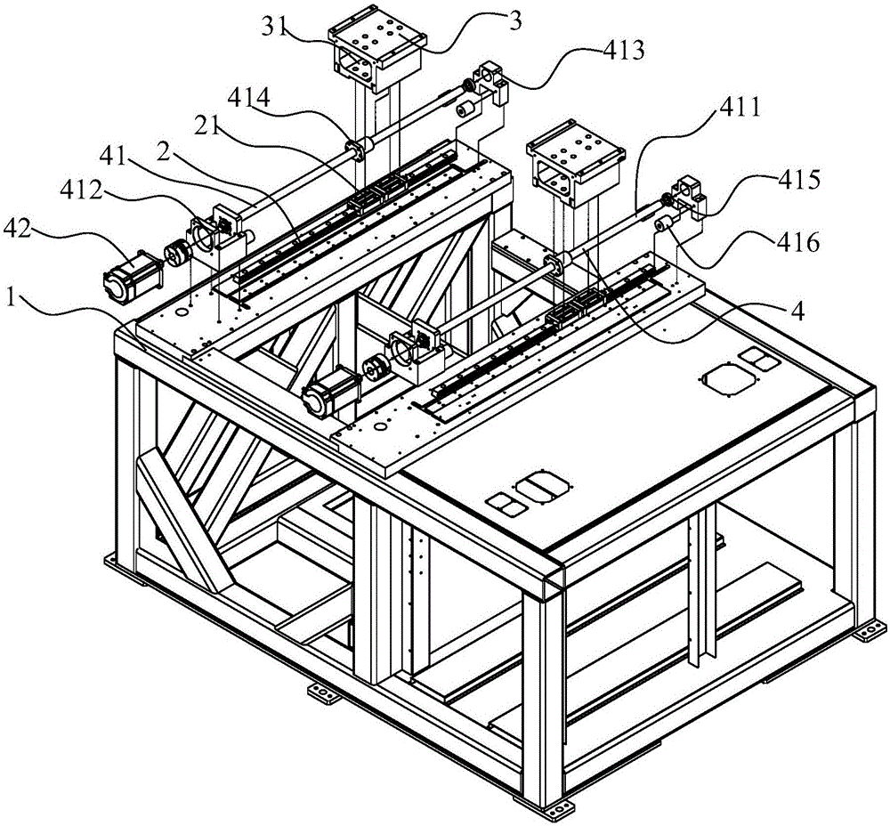
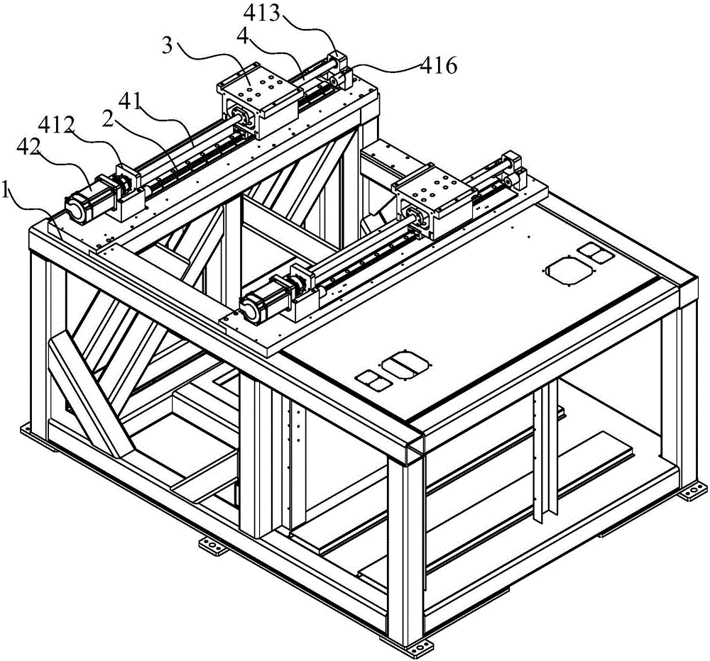
[0022] see figure 1 and figure 2 As shown, the embodiment of the present invention provides a gantry structure of a laser cutting machine, comprising: a main bed 1, two Y-axis guide rail groups 2, the two Y-axis guide rail groups 2 are arranged on the main bed body 1 in parallel with each other, and the guide rail groups There is a pair of Y-axis slide blocks 21; two Y-axis slide seats 3, the two Y-axis slide seats 3 are respectively arranged on the two Y-axis guide rail groups 2, and the Y-axis slide seats 3 are respectively arranged on the Y-axis of the Y-axis guide rail group 2 On the slider 21; two Y-axis sliding seats 3 are symmetrical along the center line of the two Y-axis guide rail groups 2; two Y-axis drive assemblies 4, each Y-axis drive assembly 4 is connected to a Y-axis sliding seat 3; Servo control device (not shown in the fig...


PUM


Abstract

The invention discloses a gantry structure for a laser cutting machine and relates to the technical field of laser cutting. The gantry structure comprises a main bed body, two Y-axis guide rail sets, two Y-axis sliding bases, two Y-axis driving components, a servo control device and a cross beam, wherein the two Y-axis guide rail sets are parallel to each other and are arranged on the main bed body; the two Y-axis sliding bases are respectively arranged on the two Y-axis guide rail sets; the two Y-axis sliding bases are symmetrical to each other along the center line of the two Y-axis guide rail sets; each of the Y-axis driving components is connected with one of the Y-axis sliding bases; the servo control device is connected with the two Y-axis driving components; the servo control device is used for controlling the two Y-axis driving components to drive the two Y-axis sliding bases to simultaneously slide along the Y-axis guide rail sets toward the same direction and at the same speed; the two ends of the cross beam are arranged on the two Y-axis sliding bases. According to the invention, the servo control device is used for controlling the two Y-axis driving components to drive the two Y-axis sliding bases to simultaneously slide along the Y-axis guide rail sets toward the same direction and at the same speed, so that the cutting efficiency and processing precision of the laser cutting machine are effectively increased.

Description

technical field [0001] The invention relates to the technical field of laser cutting, in particular to a gantry structure of a laser cutting machine. Background technique [0002] With the application of laser technology in the industrial field, many material cutting processes processed by traditional mechanical tools have been replaced by laser cutting processes. Laser cutting uses beams to replace traditional mechanical tools to realize non-contact processing. It has the characteristics of low cost, high efficiency, not limited by processing graphics style, no complicated processing programming process, and easy to realize automatic processing. At present, the traditional laser cutting machine tools on the market, the transmission mode of the main motion structure mostly adopts the transmission mode of a single set of ball screw pairs. The cutting efficiency and machining accuracy of this transmission method are not high, and it cannot meet the material processing applica...

Claims


Application Information

Patent Timeline
Patent Type & Authority Applications(China)
IPC IPC(8): B23K26/70B23K26/38
CPCB23K26/702B23K26/38
Inventor 魏刚严长军魏辉
Owner 武汉创恒世纪激光科技有限公司
Why Eureka
Try Eureka