
Rotary vertical assembling device for thin-walled barrel-shaped components

A component rotation and assembly device technology, applied to auxiliary devices, tubular objects, applications, etc., can solve the problems of inability to perform active comparison and local positioning, inability to realize multi-tube assembly, insufficient tooling flexibility, etc., to achieve the degree of equipment automation High, small footprint, reduce the effect of error factors

Active Publication Date: 2017-05-10
SHANGHAI JIAO TONG UNIV
View PDF10 Cites 10 Cited by
  • Summary
  • Abstract
  • Description
  • Claims
  • Application Information

AI Technical Summary

Problems solved by technology

[0003] The present invention can only be applied to the assembly and welding of one section of the cylinder body and the head in view of the prior art, and cannot realize the assembly between multiple cylinder sections, or the flexibility of the tooling is insufficient, and the active shape comparison and local positioning cannot be performed, and the assembly accuracy of the workpiece is very low. It largely relies on the manufacturing and installation positioning accuracy of the arc brace, lacks clamping devices, and is difficult to apply to the friction stir welding welding process that has strict requirements on fixtures and fixtures. A kind of rotary vertical assembly of thin-walled cylindrical components is proposed device

Method used


Image

  • Rotary vertical assembling device for thin-walled barrel-shaped components
  • Rotary vertical assembling device for thin-walled barrel-shaped components
  • Rotary vertical assembling device for thin-walled barrel-shaped components

Examples


Embodiment 1

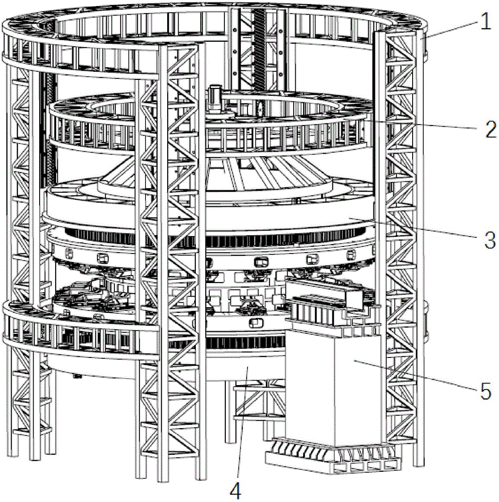
[0028] Such as figure 1 As shown, this embodiment includes: a frame 1, a vertical lifting platform 2 for lifting a cylindrical member, a friction stir welding mechanism 5, an annular upper external pressure fixture 3 and an annular lower external pressure fixture 4, wherein: the vertical lifting platform 2 , the upper external pressure fixture 3 and the lower external pressure fixture 4 are vertically and sequentially slidably arranged in the frame 1, the upper external pressure fixture 3 and the lower external pressure fixture 4 clamp and rotate the cylindrical member, and the friction stir welding mechanism 5 is fixed on the machine frame rack 1 side.

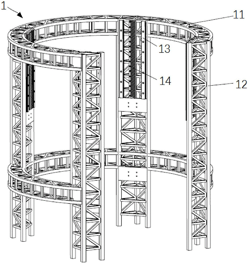
[0029] Such as figure 2 As shown, the frame 1 includes four circularly distributed uprights 12 , and the uprights 12 are provided with linear guide rails 13 and linear racks 14 which are vertically arranged. The top and middle of the column 12 form a ring through the reinforcement layer 11 of the ring truss structure. Two...


PUM


Abstract

The invention provides a rotary vertical assembling device for thin-walled barrel-shaped components. The rotary vertical assembling device comprises a machine frame, a vertical lifting platform, a mixing and friction welding mechanism, an annular upper outward-pressing clamp and an annular lower outward-pressing clamp. The vertical lifting platform is used for lifting the thin-walled barrel-shaped components. The vertical lifting platform, the annular upper outward-pressing clamp and the annular lower outward-pressing clamp are sequentially arranged in the machine frame in a sliding manner in the vertical direction. The barrel-shaped components are clamped by the annular upper outward-pressing clamp and the annular lower outward-pressing clamp, and the annular upper outward-pressing clamp and the annular lower outward-pressing clamp rotate. The mixing and friction welding mechanism is fixed on one side of the machine frame. The assembling device adopts a vertical clamping and welding way, avoids structural distortion of the thin-walled barrel-shaped components due to self gravity, and reduces the error influence factors during the assembling process; and the clamps are uniformly distributed in the circumferential direction, flexible clamping of the thin-walled barrel-shaped components is realized, the positioning precision is ensured, the clamping and positioning errors are reduced, the automatic degree of the device is high, the stations are concentrated, the occupied area is small, the height can be controlled during the processes of feeding, clamping, welding and discharging, and the assembling efficiency is improved.

Description

technical field [0001] The invention relates to a technology in the field of automatic assembly, in particular to a rotary vertical assembly device for a thin-walled cylindrical member. Background technique [0002] The high-precision assembly of large cylindrical thin-walled components is a key technology in aerospace and other fields. Aerospace thin-walled cylindrical components such as rocket storage tanks are tailor-welded with aluminum alloy thin-walled components in the form of grids in order to reduce their own weight. The assembly of large cylindrical thin-walled components mainly adopts horizontal assembly. The internal support fixture overcomes the deformation of the cylinder due to its own weight. It will increase, the cylinder structure is more seriously deformed by its own weight, and the horizontal assembly is more difficult to control the deformation of the cylinder. At the same time, the force in each direction is uneven, resulting in a decrease in positioni...

Claims


Application Information

Patent Timeline
IPC IPC(8): B23K37/04B23K37/047B23K20/12B23K101/04
CPCB23K20/12B23K37/04B23K37/0443B23K37/0461B23K37/047B23K2101/04
Inventor 王皓陈坤勇陈根良赵勇余海东来新民
Owner SHANGHAI JIAO TONG UNIV
Learn More