Ventilating system for vehicle

A ventilation system and vehicle technology, applied in the field of vehicle ventilation systems, can solve the problems of low heat dissipation efficiency in the engine compartment, increased drag coefficient, and disordered airflow field, and achieve the effects of reducing the risk of heat damage, reducing wind resistance, and reducing the drag coefficient

Active Publication Date: 2017-05-10
ZHEJIANG GEELY HLDG GRP CO LTD +1
View PDF5 Cites 12 Cited by
  • Summary
  • Abstract
  • Description
  • Claims
  • Application Information

AI Technical Summary

Problems solved by technology

In this way, although the air flow entering from the air intake grille is very large when the vehicle is running at high speed, because there is no air duct, the air flow entering the air intake grille will easily cause the airflow field to be disordered, which will lead to the cooling efficiency of the engine compartment. Lower, but also increase the drag coefficient
At the same time, due to the reduced wind flow, the heat dissipation efficiency of the engine compartment is lower when the vehicle is running at low speeds

Method used


Image

  • Ventilating system for vehicle
  • Ventilating system for vehicle
  • Ventilating system for vehicle

Examples


Embodiment Construction

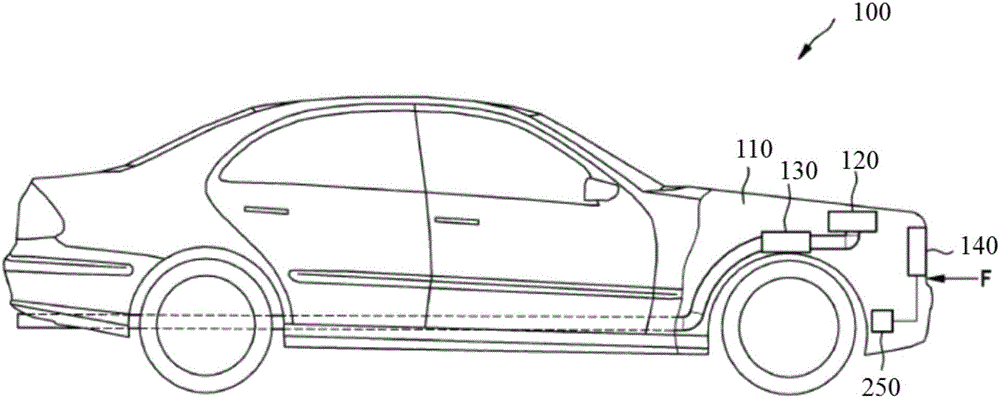
[0050] figure 1 Vehicle 100 is shown schematically with engine compartment 110 . Generally, one or more components that can dissipate heat when the vehicle 100 is running can be disposed in the engine compartment 110 , such as the internal combustion engine 120 and the exhaust device 130 . The internal combustion engine 120 exhausts combustion exhaust gas through an exhaust system 130 . The engine compartment 110 is basically closed, but there are gaps through which outside air can flow. The engine compartment 110 is generally located at the front of the vehicle 100, but is not limited thereto. The engine compartment 110 communicates with an air intake device 140 such as an air intake grill so that external air can flow through the engine compartment 110 as a headwind F.

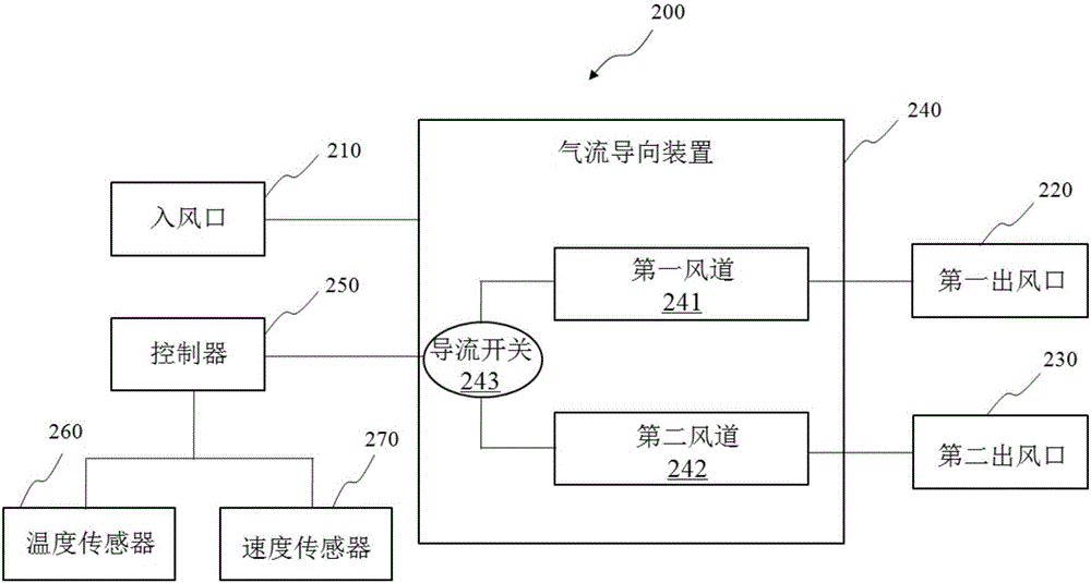
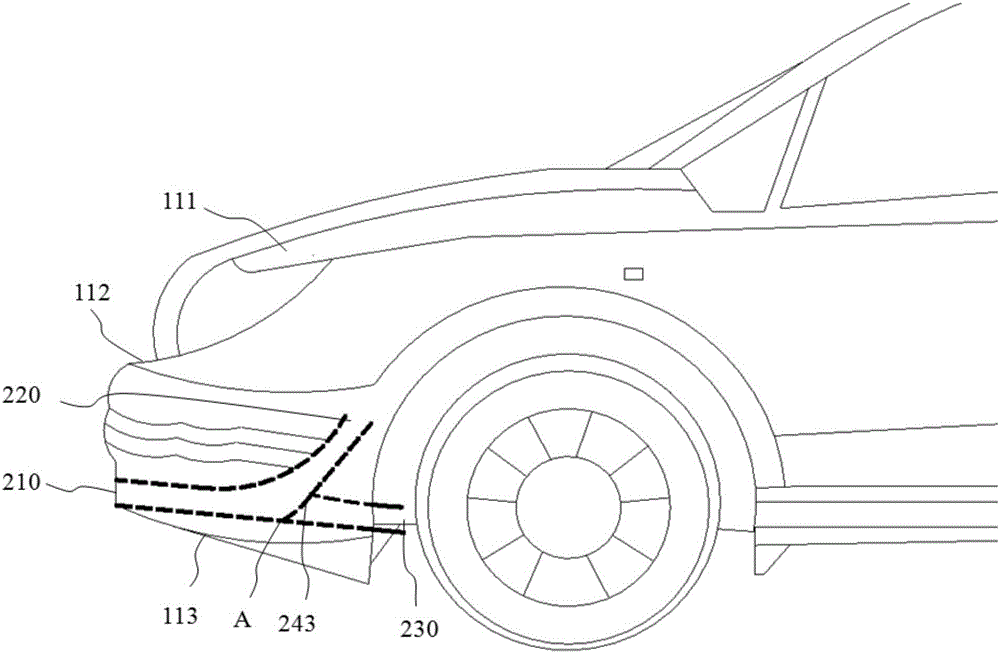
[0051] figure 2 A structural block diagram of a ventilation system 200 for a vehicle 100 according to an exemplary embodiment of the present invention is shown. image 3 and Figure 4A schematic side ...


PUM


Abstract

The invention provides a ventilating system for a vehicle. The ventilating system for the vehicle comprises an air inlet, a first air duct and a guide switch, wherein the air inlet is used for receiving outside air; the first air duct communicates with the air inlet and leads to an engine compartment; the guide switch is used for selectively closing and opening the first air duct; and the outside air enters the engine compartment through the first air duct when the first air duct is opened. By adoption of the ventilating system for the vehicle, a reasonable and effective ventilating management means which gives consideration to both the heat dissipation efficiency and the drag coefficient is provided. The wind resistance can be reduced when the vehicle travels at a high speed, and oil consumption is reduced accordingly when the vehicle travels at a high speed. Meanwhile, circulation of airflow in the engine compartment can be improved when the vehicle travels at a low speed, and the risk of heat damage in the engine compartment is lowered.

Description

technical field [0001] The invention relates to the field of vehicles, in particular to a ventilation system for vehicles. Background technique [0002] As the country's requirements on vehicle fuel consumption and emissions become more and more stringent, vehicle manufacturers are paying more and more attention to reducing fuel consumption and emissions. As a result, new technologies such as turbocharging and direct injection have been widely used, and the resulting increase in engine exhaust temperature has increased the risk of thermal management in the engine compartment. As the exhaust temperature of the engine rises, heat insulation measures need to be added in the cabin, which is not conducive to the lightweight and cost reduction of the vehicle. Moreover, when the vehicle is running at a low speed, the engine cannot dissipate heat in time due to the reduced wind flow, resulting in a decline in the overall performance of the engine and affecting its normal use. In a...

Claims


Application Information

Patent Timeline
Patent Type & Authority Applications(China)
IPC IPC(8): B60K11/08
CPCB60K11/085Y02T10/88
Inventor 杨天军梁长裘
Owner ZHEJIANG GEELY HLDG GRP CO LTD
Why Eureka
Try Eureka