Drag parachute housing with combined rear cover for aircraft

A combined, drag parachute technology, applied in aircraft parts, fuselage, parachutes, etc., can solve problems such as adverse effects on aircraft aerodynamic performance, and achieve the effects of simple structure, reduced flight resistance, and reduced probability of failure.

Pending Publication Date: 2017-05-10
CHENGDU AIRCRAFT INDUSTRY GROUP
View PDF13 Cites 2 Cited by
  • Summary
  • Abstract
  • Description
  • Claims
  • Application Information

AI Technical Summary

Problems solved by technology

[0008] The object of the present invention is to provide an aircraft drag parachute cabin with a combined back cover, which is used to solve the problem that

Method used


Image

  • Drag parachute housing with combined rear cover for aircraft
  • Drag parachute housing with combined rear cover for aircraft
  • Drag parachute housing with combined rear cover for aircraft

Examples


Embodiment 1

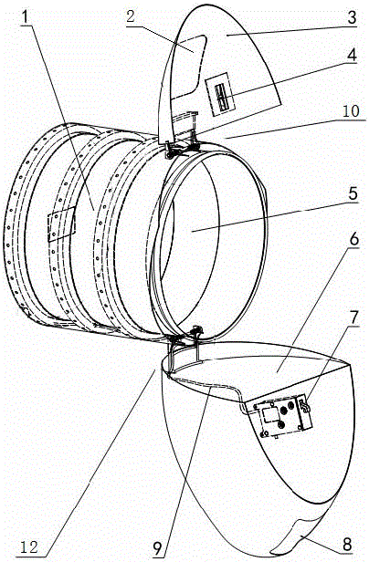
[0027] combined with Figure 1-4 Shown, a kind of aircraft resistance parachute cabin with combined back cover, comprises outer tube 1, inner tube 5, small cover shell 3, big cover shell 6, and described big cover shell 6 is provided with belt locking hook The electromagnetic unlocker 7, the small cover housing 3 is provided with a shaft pin 4, the lock hook on the electromagnetic unlocker 7 is adapted to the shaft pin 4, the electromagnetic unlocker 7 communicates with the cable 9, the The cable 9 is arranged between the outer cylinder 1 and the inner cylinder 5, the outer cylinder 1 and the inner cylinder 5 are connected by a Z-shaped rib provided on the inner cylinder, and the small cover housing 3 is hinged by the first support 10 On the inner cylinder 5 , the large cover housing 6 is hinged on the inner cylinder 5 through the second support 12 .

[0028] Technician packs resistance parachute in the present invention, manually closes large cover housing 6 and small cover ...

Embodiment 2

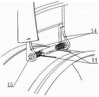
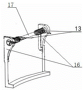
[0030] On the basis of Example 1, in conjunction with the attached Figure 1-4 As shown, the first support 10 includes a first support frame 14 and a first rotating shaft 15, the second support 12 includes a second support frame 16 and a second rotating shaft 17, and the first rotating shaft 15 and The second rotating shaft 17 is fixedly connected to the outer surface of the inner tube 5 respectively, and the first support frame 14 and the small cover housing 3, and the second support frame 16 and the large cover housing 6 pass through relatively The high-lock bolt connection with good shear resistance improves the fatigue resistance of the joint between the support frame and the shell, and enhances the durability and reliability of the components.

[0031] Further, a first torsion spring 11 is provided on the first rotating shaft 15, one end of the first torsion spring 11 is clamped on the small cover housing 3, and the other end is clamped on the outer surface of the inner c...

Embodiment 3

[0033] On the basis of embodiment 1 or 2, in conjunction with the attached Figure 1-4As shown, a first quick-release cover 2 is provided on the small cover housing 3 , and a second quick-release cover 8 is provided on the large cover housing 6 . When the present invention is maintained and maintained in the case of a power failure, the first quick release cover 2 on the small cover housing 3 and the second quick release cover 8 on the large cover housing 6 are removed, and the large cover shell is manually closed Body 6 and small cover housing 3, the lock hook on the electromagnetic unlocker 7 is inserted into the shaft pin 4 and locked automatically. The technician can check the locked situation from the first quick release port. If it is not automatically locked, it can be locked. Pull the lock hook of the electromagnetic unlocker 7 to lock it manually; when opening, those skilled in the art will put their hands into the large cover housing 6 through the second quick releas...


PUM


Abstract

The invention discloses a drag parachute housing with a combined rear cover for aircraft, relating to the field of speed-reducing assistance of the aircraft. The drag parachute housing comprises an outer drum, an inner drum, a small cover shell and a large cover shell, wherein the outer drum and the inner drum are connected by a Z-shaped rib; the large cover shell is hinged on the inner drum by a second support; the small cover shell is hinged on the inner drum by a first support; the large cover shell is provided with an electromagnetic unlocking device with a locking hook; the small cover shell is provided with a shaft pin adaptive to the locking hook on the electromagnetic unlocking device; the electromagnetic unlocking device is communicated with a cable arranged between the outer drum and the inner drum. The drag parachute housing disclosed by the invention has the advantages that the structure is simple, and excessive weight is not added; by the arrangement of an inner layer and an outer layer of the parachute housing, the unlocking and locking devices and an uncovering rotary shaft are integrated in the parachute housing, and no redundant structure is left on the surface of the parachute housing after locking, so that the adverse influence of the redundant structure on the surface of the parachute housing on the pneumatic performance of the aircraft in the prior art is solved.

Description

technical field [0001] The invention relates to the field of aircraft deceleration assistance, in particular to the field of aircraft deceleration drag parachute, specifically, an aircraft drag parachute cabin with a combined rear cover. Background technique [0002] Modern aircraft generally still maintain a higher speed when landing, so auxiliary measures are needed to shorten the landing distance of the aircraft. American aircraft mostly use speedbrakes or the simultaneous deflection of each wing surface speedbrake to act as speedbrakes to achieve aircraft deceleration, while Chinese, Russian and European aircraft mostly use drag parachutes to cooperate with fuselage speedbrakes to achieve aircraft deceleration. [0003] At present, the layout of the drag parachute cabin is divided into backpack type and built-in type. The knapsack type is to arrange the drag parachute cabin on the back of the rear fuselage, and open the cover to throw the parachute after receiving instr...

Claims


Application Information

Patent Timeline
IPC IPC(8): B64D17/80B64C1/00
CPCB64C1/00B64D17/80Y02T50/40
Inventor 游进高冠刘晓明方雄陈晓峰蒲克强
Owner CHENGDU AIRCRAFT INDUSTRY GROUP
Why Eureka
Try Eureka