
Surface treatment method for CPU cover

A technology of surface treatment and sintering treatment, which is applied in the direction of coating, metal material coating process, manufacturing tools, etc., can solve the problem of insufficient boiling performance of the CPU cover, and achieve the effects of lowering temperature, strengthening boiling performance and efficient heat dissipation

Inactive Publication Date: 2017-05-10
SUGON DATAENERGYBEIJING CO LTD
View PDF6 Cites 3 Cited by
  • Summary
  • Abstract
  • Description
  • Claims
  • Application Information

AI Technical Summary

Problems solved by technology

[0006] Aiming at the problems in the related art, the present invention proposes a surface treatment method for the CPU cover to strengthen the boiling performance of the surface of the CPU cover, thereby solving the technical problem that the existing smooth surface CPU cover has insufficient boiling performance

Method used

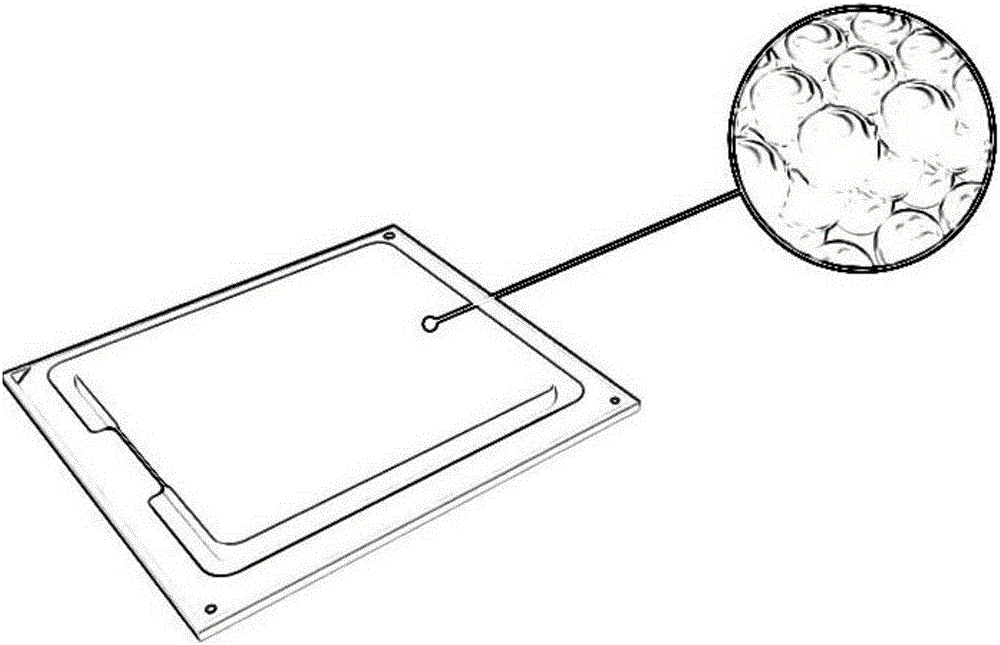

Image

  • Surface treatment method for CPU cover
  • Surface treatment method for CPU cover

Examples


Embodiment 1

[0027] Remove the rust and grease on the surface of the copper sheet, and then apply a layer of binder solution, and evenly stick the silver powder on the surface of the copper sheet. When the binder solution is air-dried, place it in a sintering furnace. Heating under the protection of hydrogen until the surface of the silver powder tends to melt, and then keep the temperature for 15 minutes to disperse and volatilize the binder, and the silver powder is sintered into one and sintered on the surface of the copper sheet, thereby forming a layer of porous metal overlay. Wherein, the thickness of the porous metal covering layer is less than 3mm, and the porosity is 40%-65%. The copper sheet is welded on the CPU cover.

Embodiment 2

[0029] Remove the rust and grease on the surface of the silver sheet, and then apply a layer of binder solution, and evenly stick the copper powder on the surface of the silver sheet. When the binder solution is air-dried, place it in a sintering furnace. Heating under the protection of hydrogen until the surface of the copper powder tends to melt, and then keep the temperature for 20 minutes to disperse and volatilize the binder, and the copper powder is sintered into one and sintered on the surface of the silver sheet, thereby forming a layer of porous metal overlay. Wherein, the thickness of the porous metal covering layer is less than 3mm, and the porosity is 40%-65%. The silver sheet is welded on the CPU cover.

Embodiment 3

[0031] Remove the rust and grease on the surface of the gold sheet, and then apply a layer of binder solution, and evenly stick the copper powder on the surface of the gold sheet. After the binder solution is air-dried, place it in a sintering furnace. Heating under the protection of hydrogen until the surface of the copper powder tends to melt, and then keep the temperature for 18 minutes to disperse and volatilize the binder, and the copper powder is sintered into one and sintered on the surface of the gold sheet, thereby forming an layer of porous metal overlay. Wherein, the thickness of the porous metal covering layer is less than 3mm, and the porosity is 40%-65%, and the gold sheet is welded on the CPU cover.


PUM

PropertyMeasurementUnit
thicknessaaaaaaaaaa
porosityaaaaaaaaaa

Abstract

The invention discloses a surface treatment method for a CPU cover. The surface treatment method comprises the following steps of evenly adhering metal powder to the surface of a sheet metal; and sintering the surface of the sheet metal under the protection of hydrogen, so as to form a porous metal covering layer on the surface of the sheet metal. The metal powder is adhered to the surface of the sheet metal to be welded on the surface of the CPU cover, the metal powder is then sintered into an integrity so as to form the porous metal covering layer on the surface of the sheet metal, and the sheet metal is welded on the CPU cover, so that the evaporation core of the CPU cover is improved, the boiling property of the surface of the CPU cover is strengthened, the surface temperature of the CPU cover is reduced, and the purposes of strengthening boiling, saving energies and efficiently dissipating heat are fulfilled.

Description

technical field [0001] The invention relates to the field of computer processing and manufacturing, more specifically, to a surface treatment method for a CPU cover. Background technique [0002] Most common computers rely on cold air to cool down the machine, and water cooling or liquid cooling has two advantages: one is that it directs the coolant to the heat source instead of indirect cooling like air cooling; the other is that compared with air cooling, each unit The heat transported by the volume, that is, the heat dissipation efficiency is as high as 3500 times. Water-cooled radiators appeared in the market around 2008. Server giants such as HP and IBM and other companies focusing on data center technology have successively launched water-cooled heat dissipation products. [0003] Evaporative cooling uses the latent heat of vaporization when the fluid boils to remove heat from the thermal principle. This cooling method using the latent heat of vaporization when the f...

Claims


Application Information

Patent Timeline
Patent Type & Authority Applications(China)
IPC IPC(8): C23C24/10B23K31/02
CPCB23K31/02C23C24/106
Inventor 沈卫东王晨吴宏杰彭晶楠李星孙振崔新涛韩磊陈进
Owner SUGON DATAENERGYBEIJING CO LTD
Learn More