Etching equipment for wafers

A technology for etching devices and wafers, applied in the directions of crystal growth, post-processing, chemical instruments and methods, etc., can solve the problems of uneven dripping of etching solution, incomplete etching of wafers, and some holes punched out of wafers, saving manpower, The effect of compact time and avoiding excessive corrosion

Active Publication Date: 2019-02-15
重庆晶宇光电科技有限公司
View PDF1 Cites 0 Cited by
  • Summary
  • Abstract
  • Description
  • Claims
  • Application Information

AI Technical Summary

Problems solved by technology

[0003] Existing wafer etching usually uses a wafer etching machine. During work, put the basket containing the wafer into the etching solution, shake the basket to etch the wafer, and put the basket into a clear water pool to clean the wafer after the etching is completed. Patent application number 201210459191.9, in the scheme of the patent name "Quartz Wafer Etching Machine", the swing mechanism is used to spray the etching solution and clear water on the basket containing the wafer, and the etching solution and clear water are sprayed on the wafer through the spray head arranged above the basket, but Spray the corrosion solution on the wafer, the corrosion solution will be sprayed onto the surface of the wafer in the form of water droplets, and the formed water drop-shaped corrosion solution will drip unevenly, part of the wafer will be sprayed with the corrosion solution, and some will not be corroded, resulting in insufficient corrosion of the wafer , it is easy for the chip to be punched out of some holes

Method used


Image

  • Etching equipment for wafers
  • Etching equipment for wafers

Examples


Embodiment Construction

[0020] The present invention will be further described in detail through specific embodiments below.

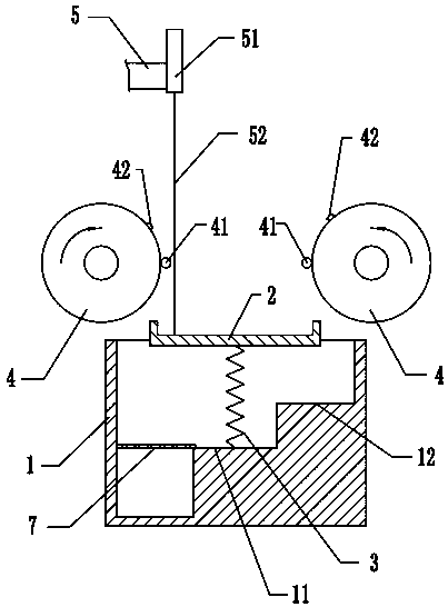
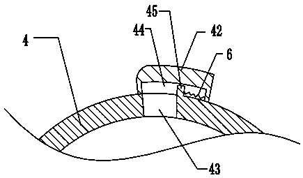
[0021] The reference signs in the accompanying drawings of the specification include: liquid pool 1, tray 2, pressure spring 3, liquid spray roller 4, water inlet 5, extension spring 6, filter screen 7, first-level high platform 11, second-level high platform 12, baffle 41. Cover 42, outlet hole 43, sliding cavity 44, post 45, sliding cover 51, pull cord 52.

[0022] like figure 1 As shown: the water outlet that can flow into clear water for cleaning the wafer is slidably connected to the slide cover 51, the lower end of the slide cover 51 is connected to one end of the stay cord 52, and the other end of the draw cord 52 is connected to one side of the tray 2, and on the side of the tray 2 There is a baffle on the periphery so that the tray 2 can hold the corrosive liquid. The drawstring 52 is in a relaxed state when there is no corrosive liquid in the tray 2. The tray 2 is ...


PUM


Abstract

The invention relates to the field of production and machining of wafers and in particular relates to a corrosion device for wafers. The corrosion device comprises a liquid tank, wherein a ladder-shaped high platform is fixedly arranged along the inner bottom of the liquid tank; the high platform comprises a first-grade high platform located in the middle of the liquid tank and a second-grade high platform higher than the first-grade high platform; the first-grade high platform is fixedly connected with a compression spring; the upper end of the compression spring is fixedly connected with a tray; a baffle is arranged at the peripheral edge of the tray; one end of the tray can be arranged on the second-grade high platform; the other end of the tray is fixedly connected with a pull rope; the pull rope is fixedly connected with a sliding cover; the sliding cover is connected onto a water inlet in a sliding manner; a liquid spraying roller capable of spraying a corrosion solution into the tray is arranged above each of two sides of the liquid tank. According to the corrosion device, the tray slightly sways leftward and the rightward, namely the corrosion solution and the wafers are correspondingly stirred, so that all the wafers and all surfaces of the wafers can be in contact with the corrosion solution, and the wafers are more uniformly corroded; after the wafers are corroded, clean water is poured to wash the wafers; the time is short and the excessive corrosion is avoided.

Description

technical field [0001] The invention relates to the field of production and processing of wafers, in particular to an etching device for wafers. Background technique [0002] The chip is a relatively important component in the LED, and it is the core part of the LED. The quality of the chip will directly determine the performance of the LED. During LED packaging, the wafers are neatly arranged on the wafer film. [0003] Existing wafer etching usually uses a wafer etching machine. During work, put the basket containing the wafer into the etching solution, shake the basket to etch the wafer, and put the basket into a clear water pool to clean the wafer after the etching is completed. Patent application number 201210459191.9, in the scheme of the patent name "Quartz Wafer Etching Machine", the swing mechanism is used to spray the etching solution and clear water on the basket containing the wafer, and the etching solution and clear water are sprayed on the wafer through the s...

Claims


Application Information

Patent Timeline
Patent Type & Authority Patents(China)
IPC IPC(8): C30B33/10
CPCC30B33/10
Inventor 侯明永
Owner 重庆晶宇光电科技有限公司
Why Eureka
Try Eureka