Grouting structure and grouting method for ground surface ultra-deep hole double liquid slurry grouting

An ultra-deep hole and dual-fluid slurry technology is applied in earthwork drilling, wellbore/well components, sealing/isolation, etc. It can solve problems such as short setting time, limited surface grouting depth, and unsatisfactory requirements. Improve grouting efficiency, good grouting effect, simple and easy construction operation

Inactive Publication Date: 2017-05-10
CHINA RAILWAY CONSTR BRIDGE ENG BUREAU GRP 2ND ENG CO LTD
View PDF7 Cites 23 Cited by
  • Summary
  • Abstract
  • Description
  • Claims
  • Application Information

AI Technical Summary

Problems solved by technology

[0003] However, since the double grout is mixed in advance and then injected into the borehole, the setting time after the double grout is mixed is very short, which limits the depth of surface grouting
At present, the depth of surface grouting can only be kept between 20 and 30m, and in some cases, the depth of grouting needs to reach more than 40 meters, which cannot meet the requirements and has certain limitations.

Method used


Image

  • Grouting structure and grouting method for ground surface ultra-deep hole double liquid slurry grouting
  • Grouting structure and grouting method for ground surface ultra-deep hole double liquid slurry grouting
  • Grouting structure and grouting method for ground surface ultra-deep hole double liquid slurry grouting

Examples


Embodiment Construction

[0037] The present invention will be described in further detail below in conjunction with the accompanying drawings.

[0038] This specific embodiment is only an explanation of the present invention, and it is not a limitation of the present invention. Those skilled in the art can make modifications to this embodiment without creative contribution as required after reading this specification, but as long as they are within the rights of the present invention All claims are protected by patent law.

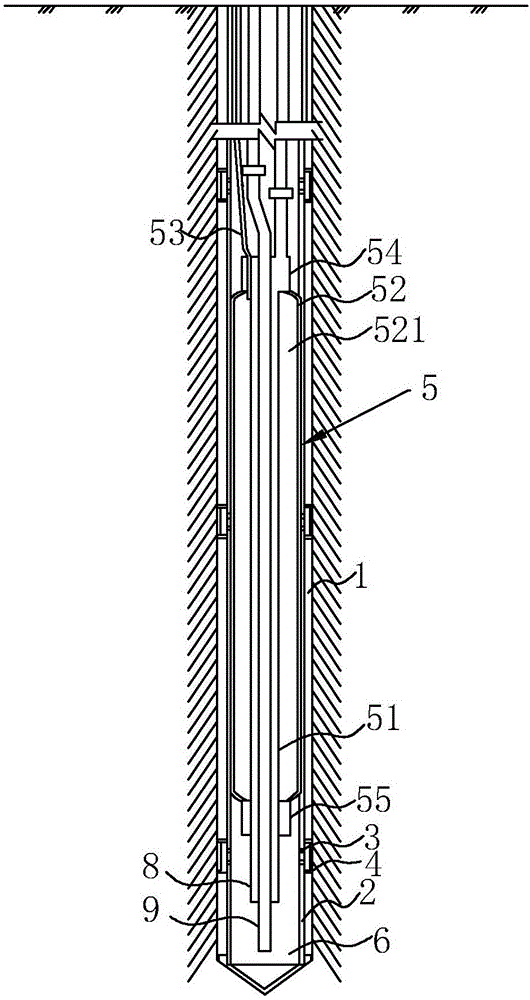
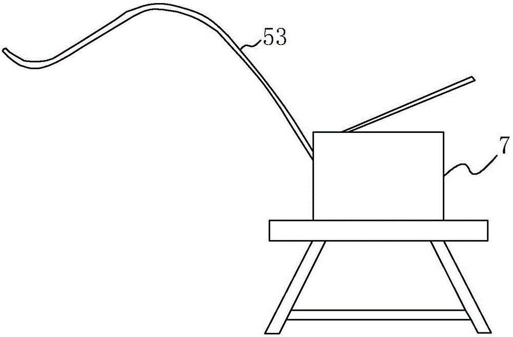
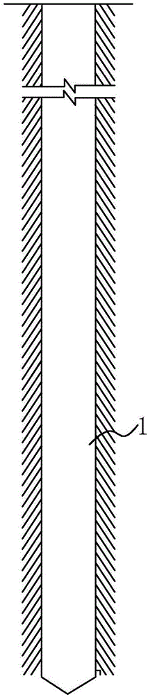
[0039] A grouting structure used for double-fluid grouting in super-deep holes on the surface, such as figure 1 and figure 2 As shown, it includes a borehole 1 opened on the surface, a sleeve valve pipe 2 is placed in the borehole 1, a grouting hole 3 is opened on the outer wall of the sleeve valve pipe 2, and the grouting hole 2 is corresponding to the sleeve valve pipe 2. Holster 4 is hooped at 3 places, and the holster 4 blocks the grouting hole 3; a stopper 5 is placed insi...


PUM


Abstract

The invention discloses a grouting structure and grouting method for ground surface ultra-deep hole double liquid slurry grouting. The structure is characterized by comprising a drill hole opened in the ground surface. A sleeve valve pipe is arranged in the drill hole. A blocking device is arranged in the sleeve valve pipe. A sealed mixing cavity is formed between the blocking device and the sleeve valve pipe bottom. A first grouting pipe and a second grouting pipe are arranged in the drill hole, and communicated with the mixing cavity. The inner wall of the mixing cavity is provided with grouting holes. The parts of the sleeve valve pipe, which correspond to the grouting hole, is bound by a leather sheath which blocks the grouting hole. The blocking device is used for sealing, and an enclosed mixing cavity is formed, thus cement slurry and sodium silicate paste are injected into the mixing cavity through the first grouting pipe and the second grouting pipe respectively to be mixed. Because the cement slurry and the sodium silicate paste are mixed at the bottom of the sleeve valve pipe, the time for mixing used in the re-transportation process is saved. Therefore, with the technical scheme, in a deeper drill hole, mixed slurry has more sufficient time to overflow from the grouting hole, and the requirement of deeper grouting can be met.

Description

technical field [0001] The invention relates to the field of double-liquid grouting, in particular to a grouting structure and a grouting method for double-liquid grouting in super-deep holes on the surface. Background technique [0002] At present, when the grouting material used for surface grouting in geotechnical engineering is cement water glass double grout, the two grouts are first mixed in the ground mixer during the construction process, and then the mixed grout is injected into the formation, such as the announcement The Chinese patent No. CN205314085U discloses a two-liquid grouting system for cement and water glass solution, including pipe A, pipe B and pipe C; pipe A is a sleeve valve pipe for injecting cement slurry; pipe B is used for The water glass is injected, and the C pipe is used to inject the casing material mud; the A pipe is arranged with multiple groups of A pipe grout holes according to the formation conditions, and each group of A pipe grout holes ...

Claims


Application Information

Patent Timeline
Patent Type & Authority Applications(China)
IPC IPC(8): E21B33/13
CPCE21B33/13
Inventor 李海阳刘鑫侯凯姚元新赵兴岩付云同周秋华肖庆贵陈仁朱
Owner CHINA RAILWAY CONSTR BRIDGE ENG BUREAU GRP 2ND ENG CO LTD
Why Eureka
Try Eureka