End surface air inlet device for rotor engine

A technology of rotary engine and air intake device, applied in combustion engine, machine/engine, internal combustion piston engine, etc., can solve the problems of sharp turn of end-face intake air flow, small inflation coefficient and average effective pressure, large fluid resistance, etc. The effect of improving the inflatable coefficient, good inflatable coefficient, and improving the inflatable coefficient

Active Publication Date: 2017-05-10
BEIJING INSTITUTE OF TECHNOLOGYGY
View PDF7 Cites 0 Cited by
  • Summary
  • Abstract
  • Description
  • Claims
  • Application Information

AI Technical Summary

Problems solved by technology

[0004] Aiming at the problems existing in the rotary engine in the prior art, such as the sharp turn of the intake air flow at the end surface, the large fluid resistance, and the low inflation coefficient and average effective pressure

Method used


Image

  • End surface air inlet device for rotor engine
  • End surface air inlet device for rotor engine
  • End surface air inlet device for rotor engine

Examples


Embodiment 1

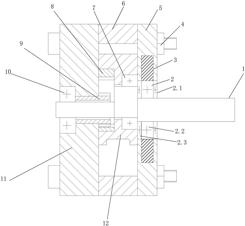
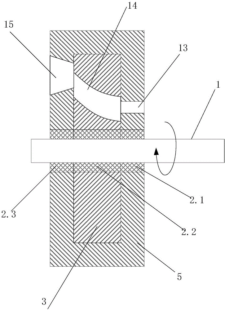
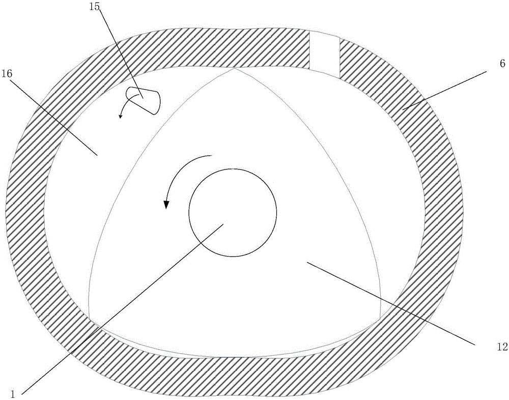
[0029] Such as figure 1 , 2 As shown, the end face air intake device for a rotary engine disclosed in this embodiment includes a crankshaft 1, a bearing 2, a first rotor 3, a bolt 4, a front end cover shell 5, a cylinder 6, a fourth bearing 7, an internal gear 8. External gear 9, fifth bearing 10, rear end cover 11, second rotor 12, first air intake 13, second air intake 14, third air intake 15 and combustion chamber 16. The front end cover includes a front end cover shell 5 and a first rotor 3, the first rotor 3 is placed in the front end cover shell 5, and the left and right sides of the front end cover shell 5 are respectively opened with a third air inlet 15 and a first air inlet 13 , the first rotor 3 has a second air inlet 14; the bearing 2 includes a first bearing 2.1, a second bearing 2.2 and a third bearing 2.3; the first bearing 2.1 cooperates with the first rotor 3, and the second bearing 2.2 , The third bearing 2.3 cooperates with the front end cover shell 5 on t...


PUM


Abstract

The invention discloses an end surface air inlet device for a rotor engine and belongs to the field of engines. The end surface air inlet device comprises a crankshaft, a bearing, a first rotor, a bolt, a front end cover casing, a cylinder, a fourth bearing, an inner gear, an outer gear, a fifth bearing, a rear end cover, a second rotor, a first air inlet channel, a second air inlet channel, a third air inlet channel and a combustion chamber, wherein a front end cover comprises the front end cover casing and the first rotor, the first rotor is arranged in the front end cover casing, the third air inlet channel and the first air inlet channel are formed in the left side and the right side of the front end cover respectively, and the second air inlet channel is formed in the first rotor; a first bearing is matched with the first rotor, and a second baring and a third bearing are matched with the front end cover casing on the left side and the right side respectively; the third air inlet channel is located above the first air inlet channel; an air outlet of the third air inlet channel is larger than an air inlet; air inlet diameter of the second air inlet channel is larger than that of the first air inlet channel. With the adoption of the end surface air inlet device for the rotor engine, fluid resistance can be reduced, and air inflow can be increased, so that air charging coefficient and mean effective pressure are increased.

Description

technical field [0001] The invention relates to auxiliary equipment for a micro-rotary engine, in particular to an end face air intake device for a rotary engine, which belongs to the field of engines. Background technique [0002] With the development of micro-electro-mechanical systems (MEMS) and the introduction of a variety of miniaturized military equipment concepts, the development of micro-energy systems with small volume, light weight, high energy density, and continuous operation has become the focus of attention of various countries. Compared with conventional portable power sources, micro-engines use hydrocarbons as fuels, which have much higher energy density, stable voltage, and low cost. Therefore, micro-engines will have wide application prospects in electronic devices in various industries such as industry, agriculture, environmental protection, medical and health care, etc., and can also directly provide power for micro-machines such as micro-cars, micro-pla...

Claims


Application Information

Patent Timeline
Patent Type & Authority Applications(China)
IPC IPC(8): F02B53/08
CPCF02B53/08Y02T10/12
Inventor 刘金祥左正兴张岩张帅
Owner BEIJING INSTITUTE OF TECHNOLOGYGY
Why Eureka
Try Eureka