
Biosafety asepsis room with monitoring function

A biosafety and sterile room technology, used in household appliances, heating methods, lighting and heating equipment, etc., can solve problems such as hidden safety hazards, interception, and difficult filtration of small organisms, and achieve reduced maintenance costs and high safety. Effect

Inactive Publication Date: 2017-05-10
合肥优亿科机电科技有限公司
View PDF7 Cites 4 Cited by
  • Summary
  • Abstract
  • Description
  • Claims
  • Application Information

AI Technical Summary

Problems solved by technology

[0006] The existing aseptic rooms on the market all use filters as the dust filtration method. This method can no longer meet the requirements for many biomedical production lines with high cleanliness requirements, such as phages, viruses, some bacteria, etc. A tiny organism that is difficult to retain by filtration
Moreover, the cleaning of sterile room filters with a large number of virus microorganisms is also one of the difficulties.
Many biopharmaceutical companies are based on the consideration of reducing filter maintenance costs, so that the cleanliness level of the clean room often does not meet the requirements for use
[0007] In addition, for biological laboratories with potential, high or unknown transmission routes, ordinary safety laboratories usually use micro-negative pressure to prevent the spread of pathogenic microorganisms, which has potential safety hazards and insufficient protection for experimenters. The filter fails, and the pathogenic microorganisms in the air are repeatedly circulated in the air, and the chance of harm to people increases

Method used


Image

  • Biosafety asepsis room with monitoring function
  • Biosafety asepsis room with monitoring function
  • Biosafety asepsis room with monitoring function

Examples


Embodiment Construction

[0020] Below in conjunction with the drawings and specific embodiments, the present invention will be described in detail. Before describing the technical solutions of the various embodiments of the present invention in detail, the terms and terms involved will be explained. In this specification, the same name or the same number Components represent similar or identical structures and are for illustrative purposes only.

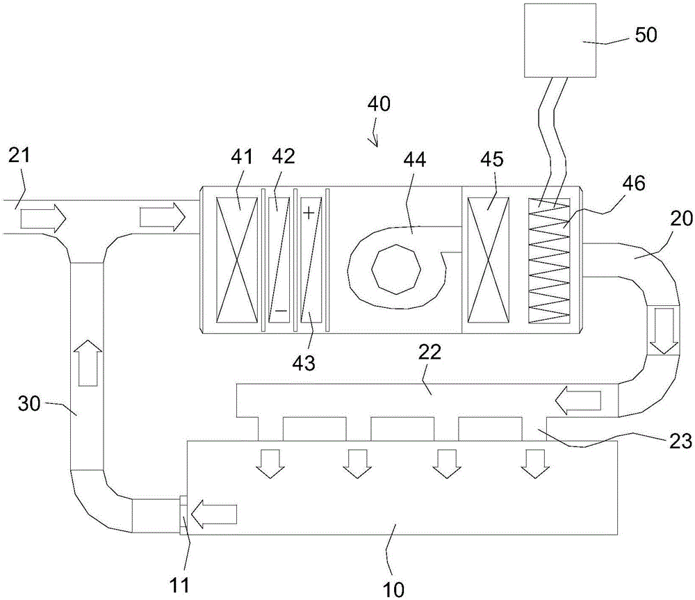
[0021] Such as figure 1 As shown, the biological safety level sterile room includes an aseptic operation room 10, an air supply pipe 20, a return air pipe 30, and a purifier 40 arranged in the air supply pipe. The air inlet 21 of the air supply pipe communicates with the outside, The air outlet 22 of the air supply pipe communicates with the aseptic operation room, and the air return port 11 of the aseptic operation room communicates with the air inlet of the air supply pipe through the air return pipe, and the air supply pipe communicates with the aseptic o...


PUM


Abstract

The invention discloses a biosafety asepsis room with a monitoring function. The biosafety asepsis room with the monitoring function comprises an aseptic processing room, an air supply pipe, an air returning pipe and a purifier, wherein the purifier is placed in the air sending pipe. An air inlet of the air supply pipe is communicated outdoor, an air outlet of the supply pipe is communicated to the aseptic processing room, and an air returning inlet of the aseptic processing room is communicated to the air inlet of the air supply pipe. The purifier comprises a low efficient filter, a cooling tower, a heater, a draught fan, a medium efficiency filter and a plasma sterilizer placed in the gas flowing direction in sequence, and a monitoring upper computer used for monitoring the plasma sterilizer, and the plasma sterilizer detects current, voltage, density and electron energy of the plasma, and monitors whether a purifying unit is in a working state or not in real time. According to the biosafety asepsis room with the monitoring function, firstly, large particles in the air are firstly filtered out, then sterilization is conducted through a plasma method, thus it is guaranteed that recirculating air in the asepsis room is sterile and nontoxic, and the demand of many bio-pharmaceutical enterprises for biosafety grade asepsis room is met.

Description

technical field [0001] The invention relates to the technical field of biopharmaceutical equipment, in particular to a high-safety aseptic room with monitoring function, and also covers other biomedical production, operation or circulation spaces outside the aseptic room, including aseptic rooms, inoculation rooms, transfer Windows, clean sheds, etc. The fields include electronic information, semiconductors, optoelectronics, precision manufacturing, medicine and health, bioengineering, aerospace, automotive spraying, fine chemicals, food and beverages and other clean environments with high requirements. Background technique [0002] Sterile rooms are generally dedicated to microbiology laboratories and can be constructed of plates and glass. A buffer room should be set up outside the sterile room, and the doors should be staggered to prevent airflow from bringing in bacteria. Both the sterile room and the buffer room must be airtight, and the ventilation equipment equippe...

Claims


Application Information

Patent Timeline
IPC IPC(8): F24F7/08F24F3/16A61L9/22
CPCA61L9/22F24F3/16F24F7/08F24F3/167F24F8/30
Inventor 滕海燕
Owner 合肥优亿科机电科技有限公司
Learn More