Composite heat exchanger for organic Rankine cycle power generating system

A heat exchanger and Rankine cycle technology, applied in the field of composite heat exchangers, can solve problems such as difficult, difficult to realize, and flow rate differences, and achieve the effect of reliable heat exchangers and small volumes

Inactive Publication Date: 2017-05-10
潍坊小禾节能科技有限公司
View PDF11 Cites 4 Cited by
  • Summary
  • Abstract
  • Description
  • Claims
  • Application Information

AI Technical Summary

Problems solved by technology

[0007] like figure 2 and image 3 The plate-fin heat exchanger shown includes liquid-phase sensible heat zone, gas-liquid latent heat zone and gas-phase sensible heat zone. When the heat exchanger is used, the plate-fin heat exchanger will face the difficult problem of ensuring the best heat exchange effect in all sections
Even if the same fluid medium flows, the flow velocity in the same flow channel is significantly different due to the huge difference in density between the liquid phase and the gaseous state. ...

Method used


Image

  • Composite heat exchanger for organic Rankine cycle power generating system
  • Composite heat exchanger for organic Rankine cycle power generating system
  • Composite heat exchanger for organic Rankine cycle power generating system

Examples


Embodiment 1

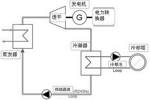
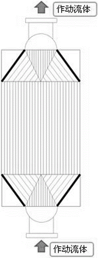
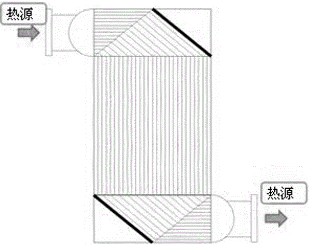
[0028] Example 1, such as Figure 4 , Figure 5 As shown, a composite heat exchanger for an organic Rankine cycle power generation system includes a liquid-phase sensible heat zone 1, a gas-liquid latent heat zone 2, and a gas-phase sensible heat zone 3.

[0029] The liquid-phase sensible heat zone 1 is arranged at the bottom of the heat exchanger. The liquid-phase sensible heat zone 1 is ring-shaped, and the liquid-phase sensible heat zone 1 is where the flow medium undergoing phase change undergoes heat exchange from a liquid-phase state.

[0030] The gas-liquid latent heat zone 2 is arranged in parallel with the liquid-phase sensible heat zone 1, and the annular inner surrounding space of the liquid-phase sensible heat zone 1 is the gas-liquid latent heat zone 2, and the gas-liquid latent heat zone 2 and the liquid-phase sensible heat zone 1 are connected. , the gas-liquid latent heat zone 2 has a larger cross-sectional area than the liquid-phase sensible heat zone 1, and ...

Embodiment 2

[0032] Example 2, such as Figure 4 , Figure 5 , Figure 6 As shown, a composite heat exchanger for an organic Rankine cycle power generation system includes a liquid-phase sensible heat zone 1, a gas-liquid latent heat zone 2, and a gas-phase sensible heat zone 3.

[0033] The liquid-phase sensible heat zone 1 is arranged at the bottom of the heat exchanger. The liquid-phase sensible heat zone 1 is ring-shaped, and the liquid-phase sensible heat zone 1 is where the flow medium undergoing phase change undergoes heat exchange from a liquid-phase state.

[0034] The gas-liquid latent heat zone 2 is arranged in parallel with the liquid-phase sensible heat zone 1, and the annular inner surrounding space of the liquid-phase sensible heat zone 1 is the gas-liquid latent heat zone 2, and the gas-liquid latent heat zone 2 and the liquid-phase sensible heat zone 1 are connected. , the gas-liquid latent heat zone 2 has a larger cross-sectional area than the liquid-phase sensible heat...


PUM


Abstract

The invention discloses a composite heat exchanger for an organic Rankine cycle power generating system. The composite heat exchanger comprises a liquid-phase sensible heat area, a gas-liquid latent heat area and a gas-phase sensible heat area, wherein the cross section area of the liquid-phase sensible heat area, the gas-liquid latent heat area and the gas-phase sensible heat area is different. The composite heat exchanger has the advantages that the liquid-phase sensible heat area, the gas-liquid latent heat area and the gas-phase sensible heat area are separated, optical cross section area of the liquid-phase sensible heat area, the gas-liquid latent heat area and the gas-phase sensible heat area is achieved, certain flow speed is maintained, the heat exchanger is reliable and small in size, the efficiency of the organic Rankine cycle power generating system is improved to the maximum extent, and equipment cost is reduced.

Description

technical field [0001] The invention relates to a composite heat exchanger for an organic Rankine cycle power generation system, belonging to the technical field of mechanical equipment. Background technique [0002] Such as figure 1 As shown, the organic Rankine cycle power generation system is composed of a working fluid pump, evaporator, turbine-generator, condenser, receiving container, etc. The working principle is as follows: firstly, the high-pressure compressed liquid-phase organic working medium is delivered to the evaporator by the working medium pump, and the high-pressure liquid phase delivered to the evaporator is evaporated into a high-pressure gas by the heat source of the evaporator. Subsequently, the high-pressure gas expands into a low-temperature, low-pressure gas through the turbine of the turbo-generator, and powers the turbine, which is transmitted to the generator to generate electricity. The low-temperature, low-pressure operating fluid that becomes...

Claims


Application Information

Patent Timeline
IPC IPC(8): F25B39/02F25B39/04
CPCF25B39/022F25B39/04F25B2339/02F25B2339/043
Inventor 王芳崔相现李明阳
Owner 潍坊小禾节能科技有限公司
Why Eureka
Try Eureka