
Test method for uniaxial constitutive relation of ductile material

A technology of constitutive relation and ductile material, applied in the direction of analyzing materials, applying stable tension/pressure to test the strength of materials, measuring devices, etc., can solve the problems of engineering stress drop and the inability to truly obtain the stress-strain relationship of materials, etc., to achieve The effect of avoiding severe effects, simple and easy method, and wide range of constitutive relations

Active Publication Date: 2017-05-10
SOUTHWEST JIAOTONG UNIV
View PDF8 Cites 13 Cited by
  • Summary
  • Abstract
  • Description
  • Claims
  • Application Information

AI Technical Summary

Problems solved by technology

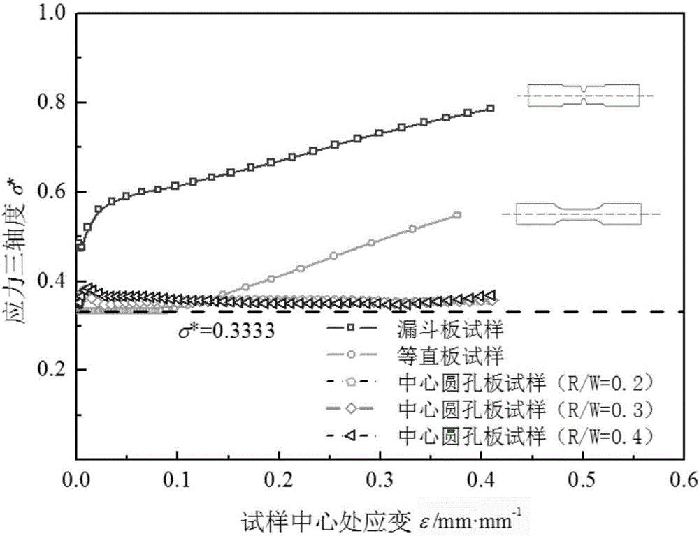
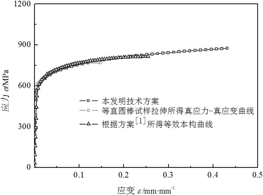
[0002] The uniaxial constitutive relationship of ductile materials (i.e., the tensile stress-strain relationship) is the basic physical relationship for structural analysis and engineering design using the continuum mechanics method, and is also an important "link" linking materials and mechanics. and safety evaluation play a key role; in the traditional tensile test, the real cross-sectional area and gauge length of the straight section of the sample are constantly changing during the tensile test, after the sample appears necking, the necking position The material is no longer in plane deformation, and the engineering stress-strain curve of the gauge section shows a trend that the engineering stress decreases sharply with the increase of the test strain; in fact, although the response load will decrease after the sample is necked, the material is However, it is still hardening during the process, and the real stress is constantly increasing. The center point of the cross-section of the necking area of ​​the sample is already in a triaxial stress state; The stress-strain relationship of

Method used


Image

  • Test method for uniaxial constitutive relation of ductile material
  • Test method for uniaxial constitutive relation of ductile material
  • Test method for uniaxial constitutive relation of ductile material

Examples


Embodiment Construction

[0029] The present invention will be further described below in conjunction with the accompanying drawings and specific embodiments.

[0030] A method for testing the uniaxial constitutive relationship of ductile materials, comprising the following steps:

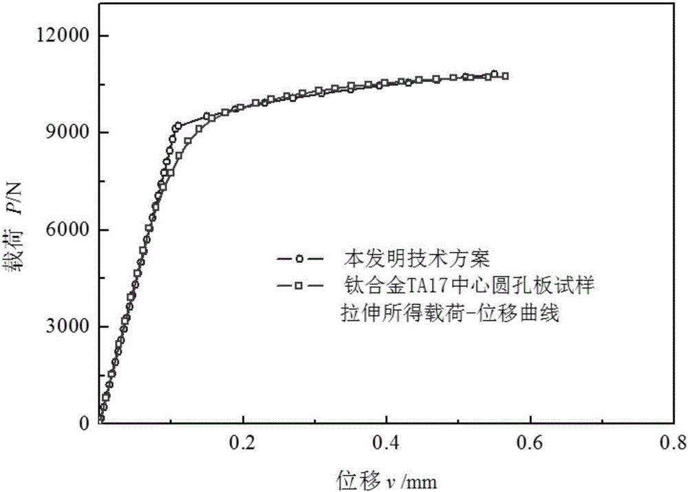
[0031] Through the quasi-static tensile test, the relationship between the continuous load P and the displacement V of the material sample is obtained. The sample is a central circular hole plate sample, and the P-V curve satisfies the following relationship:

[0032]

[0033] In the formula: R sample hole radius, S is the elastic stiffness, P* is the characteristic load, m is the displacement index, V y is the yield displacement of the sample;

[0034] Obtain the constitutive relation parameters of the material according to S, P* and m, including elastic modulus E, nominal yield stress σ y and the strain hardening exponent n, the critical fracture stress σ is obtained by finite element simulation f and the critical f...


PUM


Abstract

The invention discloses a method for determining the large deformation uniaxial constitutive relation of a material based on the energy principle and a P-V curve obtained by stretching a central circular hole plate specimen. The method comprises the following steps: performing quasi-static tensile test on a central circular hole plate specimen to obtain a continuous P-V curve, and determining the elastic stiffness S, the feature load P* and the displacement index m by the curve so as to obtain the large deformation uniaxial constitutive relation of the material. The method disclosed by the invention is applicable to a ductile material with an isotropic strengthening and constitutive relation according with the power law, wherein the structure of the central circular hole plate specimen is special, namely during the tensile test, the circular hole edge center point material unit of the specimen is under uniaxial stress state before the occurrence of necking; compared with an equidistant specimen, the method disclosed by the invention is easier to implement, and the obtained uniaxial stress-strain relation is wider in range; the method has great significance on the engineering structure design and safety assessment work.

Description

technical field [0001] The invention relates to the testing of mechanical properties of materials, in particular to a method for testing the uniaxial constitutive relationship of ductile materials. Background technique [0002] The uniaxial constitutive relationship of ductile materials (i.e., the tensile stress-strain relationship) is the basic physical relationship for structural analysis and engineering design using the continuum mechanics method, and is also an important "link" linking materials and mechanics. and safety evaluation play a key role; in the traditional tensile test, the real cross-sectional area and gauge length of the straight section of the sample are constantly changing during the tensile test, after the sample appears necking, the necking position The material is no longer in plane deformation, and the engineering stress-strain curve of the gauge section shows a trend that the engineering stress decreases sharply with the increase of the test strain; i...

Claims


Application Information

Patent Timeline
IPC IPC(8): G01N3/08
CPCG01N3/08G01N2203/0017
Inventor 于思淼蔡力勋陈辉包陈姚迪
Owner SOUTHWEST JIAOTONG UNIV
Learn More