Spatial filtering speed measurer based on digital micro mirror

A speed measuring device and digital micromirror technology, which is applied in measuring devices, devices using optical methods, fluid velocity measurement, etc., can solve problems such as overexposure and partial underexposure, and achieve the effect of improving accuracy and increasing the measurable range

Pending Publication Date: 2017-05-10
EAST CHINA NORMAL UNIV
View PDF0 Cites 4 Cited by
  • Summary
  • Abstract
  • Description
  • Claims
  • Application Information

AI Technical Summary

Problems solved by technology

Without artificial lighting, images can be partially underexposed or overexposed due to highly dynamic switching between sunlight and shadows

Method used


Image

  • Spatial filtering speed measurer based on digital micro mirror
  • Spatial filtering speed measurer based on digital micro mirror
  • Spatial filtering speed measurer based on digital micro mirror

Examples


Embodiment

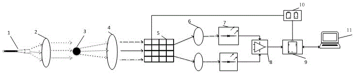
[0039] Take a moving ball as an example, see Figure 4 , the concrete working process of the present invention:

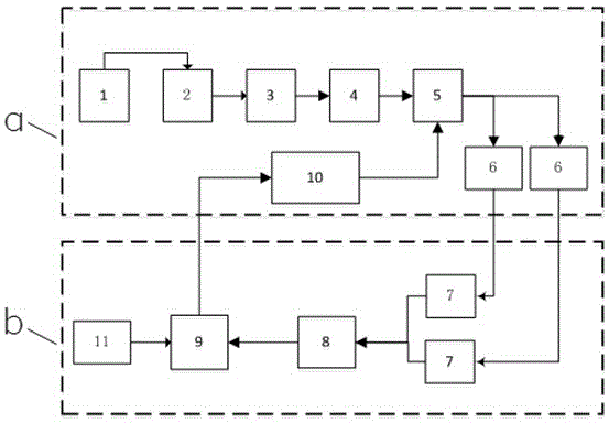
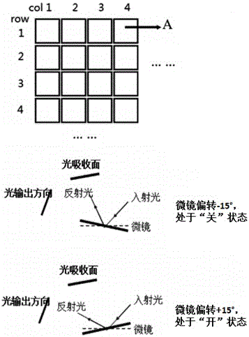
[0040] Power-on initialization, PC 11 communicates with signal processing board 9 by MCU, the operating mode of signal processing board 9 is set, after signal processing board 9 starts working, the signal of control digital micromirror device 5 operating modes is sent to drive circuit 10, The driving circuit 10 drives the digital micromirror device 5 to work, and deflects the tiny mirrors on the digital micromirror device 5 to form two groups of gratings. The light source 1 is incident on the collimating lens 2, and the collimating lens 2 turns the light source 1 into a parallel light incident on the small ball 3, and the small ball 3 forms an image through the lens 4, and the formed image is incident on the digital micromirror device 5, and the digital micromirror device 5 The micromirror device 5 reflects the grouped images of the incident small ball 2 onto the ...


PUM


Abstract

The invention discloses a spatial filtering speed measurer based on a digital micro mirror. The device comprises a light source, a collimating lens, a moving object, a lens, a digital micro mirror device, a focusing lens, a driver circuit, a photoelectric detector, a differential circuit, a signal processing board, a driver circuit, and a PC. The working process of the device is as follows: an image of the object is projected to the digital micro mirror device, and the digital micro mirror device filters incoming light; filtered optical signals are focused and then incident on the photoelectric detector, and the photoelectric detector converts the optical signals into electrical signals; and the signal processing board processes the electrical signals to get the speed of the object. The problem that the spacing of gratings and the number of gratings in the existing spatial filtering speed measurer cannot be adjusted is solved. Moreover, spatial filtering is divided into two groups, and part of interference is eliminated. The invention provides a high-precision spatial filtering speed measurer.

Description

technical field [0001] The invention relates to the field of space filter speed measurement, in particular to a space filter speed measurement device based on a digital micromirror. Background technique [0002] The basic concept of spatial filtering speed measurement comes from aerial camera control technology and infrared optical tracking technology. An image enhancement method using filter processing, the theoretical basis of which is spatial convolution. The purpose is to improve image quality, including removal of high-frequency noise and interference, image edge enhancement, linear enhancement, and deblurring. Compared with traditional methods, optical measurement speed has very important advantages, such as non-contact and non-interference. Spatial filtering technology can be used to measure the speed detection of solid objects such as ships, automobiles, airplanes, rockets, wind turbines, ship propellers, and aircraft rotating shafts; the speed detection of liquid ...

Claims


Application Information

Patent Timeline
Patent Type & Authority Applications(China)
IPC IPC(8): G01P3/36G01P5/26
CPCG01P3/366G01P5/26
Inventor 刘一清刘瑞芳
Owner EAST CHINA NORMAL UNIV
Why Eureka
Try Eureka