Online detection method of wave aberration of projection objective of lithography machine for self-calibrating system error

A projection objective and system error technology, applied in the field of optical inspection, can solve the problems of calibration system error, limit the detection accuracy of projection objective wave aberration, cannot eliminate the residual aberration of the illumination system, etc., achieve high-precision separation, ensure utilization, Realize the effect of spatial filtering

Active Publication Date: 2013-06-05
BEIJING INSTITUTE OF TECHNOLOGYGY
View PDF1 Cites 2 Cited by
  • Summary
  • Abstract
  • Description
  • Claims
  • Application Information

AI Technical Summary

Problems solved by technology

However, since this method uses a square hole to expand the light source, the residual aberration of the illumination system cannot be eliminated, and the system error is calibrated by axially moving the image square hole mask. The axial movement range of the mask plate limits the spatial filtering effect of the image square square hole mask plate on the wave aberration of the lithography projection objective lens and the residual aberration of the illumination system
Due to the above two deficiencies, to a certain extent, the detection accuracy of using this method to detect the wave aberration of the projected objective lens is limited.

Method used


Image

  • Online detection method of wave aberration of projection objective of lithography machine for self-calibrating system error
  • Online detection method of wave aberration of projection objective of lithography machine for self-calibrating system error
  • Online detection method of wave aberration of projection objective of lithography machine for self-calibrating system error

Examples


Embodiment Construction

[0031] The present invention will be described in further detail below in conjunction with the accompanying drawings.

[0032] Firstly, the structural composition and working principle of the lithography machine are explained:

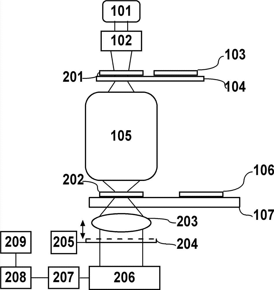
[0033] The lithography machine includes an exposure light source 101, an illumination system 102, a mask plate 103, an object-space workpiece stage 104, a projection objective lens 105, a silicon wafer 106, and an image-space workpiece stage 107; On the mask plate 103 , the pattern on the mask plate 103 is shrunk and projected onto the silicon wafer 106 coated with photoresist through the projection objective lens 105 in a step-and-scan manner to realize pattern transfer. The exposure light source 101 is an ArF excimer laser with a wavelength of about 193 nm or a KrF excimer laser with a wavelength of about 248 nm. The illumination system 102 has an optical element for expanding the beam, adjusting the steering and shape of the beam, and an optical el...


PUM


Abstract

The invention provides an online detection method of wave aberration of a projection objective of a lithography machine for self-calibrating system error. The method comprises the following steps of: adopting an object space mask plate which is provided with square pinhole arrays; and adopting the square pinhole arrays to generate ideal spherical waves so as to eliminate the influences of an illuminating system on detection of the wave aberration of the projection objective of the lithography machine. By the system error self-calibration filtered by the pinhole arrays, square holes are arranged on object surface of the projection objective of the lithography machine, and the pinhole arrays are arranged on the image surface so that the use ratio of exposure light source is guaranteed; the spatial filtering is performed to residual aberration of the to-be-detected illuminating system and the wave aberration of the projection objective; and by the method in the invention, the wave aberration of the projection objective is rapidly separated from the system error of an online detection apparatus with high accuracy.

Description

technical field [0001] The invention belongs to the technical field of optical detection, and in particular relates to an online detection method for the wave aberration of a projected objective lens of a photolithography machine with self-calibration of system errors. Background technique [0002] With the improvement of lithography resolution, the residual wave aberration of the projection objective lens of lithography machine is required to be smaller and smaller. The three major companies ASML, Canon and Nikon directly use high-precision phase measurement interferometers (PMI for short) when processing and integrating projection objective lenses for lithography machines, such as Tieman-Green interferometers and Fizeau interferometers. The residual wave aberration of the engraving machine projection objective lens is detected. However, in practice, due to factors such as transportation and assembly, the wave aberration of the objective lens projected by the lithography m...

Claims


Application Information

Patent Timeline
Patent Type & Authority Patents(China)
IPC IPC(8): G03F7/20G01M11/02
Inventor 李艳秋汪海刘克
Owner BEIJING INSTITUTE OF TECHNOLOGYGY
Why Eureka
Try Eureka