Optical module
A technology of optical modules and optical sub-modules, applied in the field of optical modules, can solve problems such as EMC performance that cannot meet the specified requirements, electromagnetic compatibility) performance defects, etc., to achieve the effect of reducing electromagnetic radiation and improving EMC performance
- Summary
- Abstract
- Description
- Claims
- Application Information
AI Technical Summary
Problems solved by technology
Method used
Image

Examples
Embodiment Construction
[0024] The present invention will be further elaborated below in conjunction with the accompanying drawings.
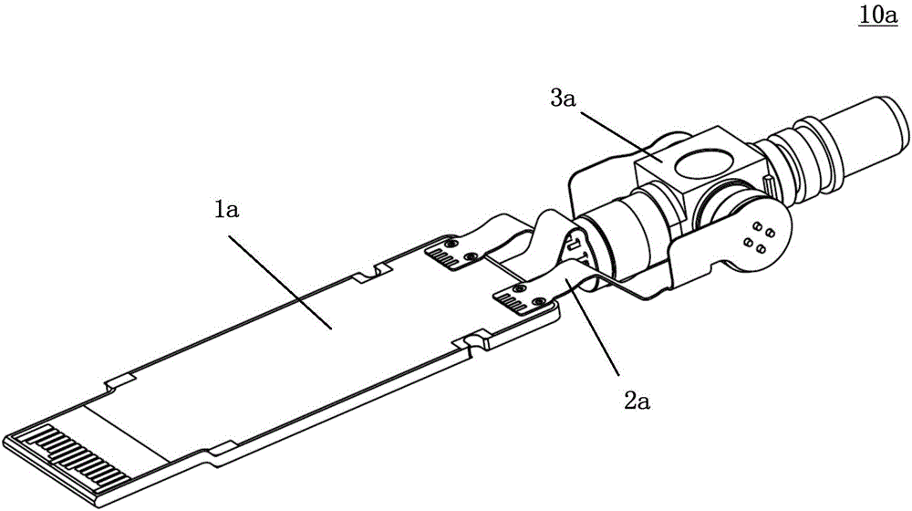
[0025] see Figure 5 , Figure 5 It is a structural representation of an embodiment of the optical module of the present invention. The present invention proposes an optical module 10, which includes: a circuit board 2, a gold finger 4 arranged at one end of the circuit board 2, and an optical chip arranged on the circuit board 2 in the form of COB (Chip On Board, chip on board) 5. Encapsulation structure 6 and optical connector 7 . Such a structure of the optical module 10 is beneficial to the miniaturization and compactness of the optical module 10 by integrating the optical chip 5 and the circuit board 2 , and can increase the application range of the optical module 10 .
[0026] see Image 6 , Image 6 yes Figure 5 The working principle of the shielding cage of the circuit board in the optical module shown is schematic. The circuit board 2 is a multi-layer...
PUM
 Abstract
Description
Claims
Application Information