Compound-eye light homogenization system, optical engine and light source optimization device

A technology of optical system and compound eye, which is applied in the direction of photolithography exposure device, optics, microlithography exposure equipment, etc., can solve the problems of uneven energy distribution and high scrap rate of PCB boards, etc.

Inactive Publication Date: 2017-05-10
TIANJIN JINXIN MICROELECTRONICS TECH CO LTD
View PDF6 Cites 0 Cited by
  • Summary
  • Abstract
  • Description
  • Claims
  • Application Information

AI Technical Summary

Problems solved by technology

[0003] In view of this, the object of the present invention is to provide a compound eye uniform light system, an optical engine and a light source optimization device to solve the problem of uneven energy distribution during DI exposure in the compound eye uniform light system in the prior art, which leads to PCB board scrap rate Persistent problem

Method used


Image

  • Compound-eye light homogenization system, optical engine and light source optimization device
  • Compound-eye light homogenization system, optical engine and light source optimization device
  • Compound-eye light homogenization system, optical engine and light source optimization device

Examples


Embodiment 1

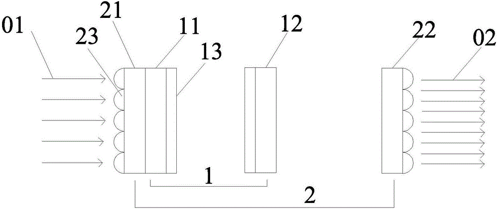
[0038] Such as figure 1 As shown, the compound eye homogenization system provided by the present invention includes a first lens group 1 and a second lens group 2, the first lens group 1 includes a second lens 11 and a third lens 12, and the second lens group 2 includes a first lens 21 and the fourth lens 22 .

[0039] The parallel incident light 01 passes through the first lens 21 , the second lens 11 , the third lens 12 and the fourth lens 22 in sequence.

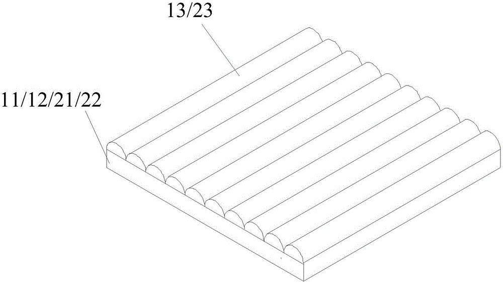
[0040] The light exit surface of the second eyeglass 11 and the light entrance surface of the third eyeglass 12 are all provided with a first fly-eye lens array 13; the light entrance surface of the first eyeglass 21 and the light exit surface of the fourth eyeglass 22 are all provided with a second fly eye lens array 23 ; the first fly-eye lens array 13 is perpendicular to the second fly-eye lens array 23 .

[0041] The focus of each small lens in the second fly-eye lens array 23 of the first eyeglass 21 coincides with...

Embodiment 2

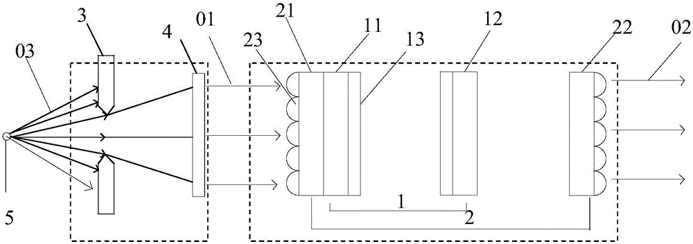
[0047] A DI device often contains more than two similar optical engines. The optical engine provides the source of light energy for DI. After the optical engine, it will go through a series of optical components. The differences between the optical engine itself and the subsequent optical devices will Causes the difference in energy reaching the exposure surface workbench. The optical engine can adjust this difference without affecting other performance of the device.

[0048] Most DI equipment adopts DMD imaging technology, limited to the size of the DMD frame, a DI equipment often needs multiple identical optical lens modules, which puts higher requirements on the optical engine contained in each lens module, requiring optical The engine performance is stable, and the energy is flexible and adjustable. Finally, it is ensured that the energy is uniform within the range of the DI imaging exposure area. The invention provides an optical engine with adjustable energy.

[0049...

Embodiment 3

[0062] A DI device often contains more than two similar light source optimization devices, which provide light energy sources for DI, and then pass through a series of optical components. The light source optimization device has its own differences. And the difference of subsequent optical devices will cause the difference of imaging quality reaching the exposure surface workbench. The light source optimization device can optimize this difference without affecting other performances of the equipment.

[0063] DI equipment involves DMD projection technology and optical imaging system. In optical imaging, the imaging quality of different wavelengths has certain differences. If the wavelength bandwidth of the light source is narrow enough, the imaging quality will be better, which has a better effect on the light source before reaching the imaging system. demanding. It is required that the wavelength of the light source is single and the performance is stable, so as to finally e...


PUM


Abstract

The invention provides a compound-eye light homogenization system, an optical engine and a light source optimization device and relates to the technical field of photoetching direct writing exposure machines and projection display. According to the compound-eye light homogenization system provided by the invention, parallel incident light passes through a first lens, a second lens, a third lens and a fourth lens in sequence; first compound-eye lens arrays are arranged on opposite surfaces of the second lens and the third lens; second compound-eye lens arrays are arranged on departure surfaces of the first lens and the fourth lens; a focus point of each small lens in the second compound-eye lens array of the first lens is overlapped with an optical center of a corresponding small lens in the first compound-eye lens array of the second lens; and the focus point of each small lens in the first compound-eye lens array of the third lens is overlapped with optical center of the corresponding small lens in the second compound-eye lens array of the fourth lens. According to the compound-eye light homogenization system provided by the invention, the problem that energy distribution is not uniform in a DI exposure process is solved; effective homogenization of light can be realized; and needed uniform energy can be obtained in the final DI exposure process.

Description

technical field [0001] The invention relates to the technical field of photolithography direct writing exposure machine and projection display, in particular to a compound eye uniform light system, an optical engine and a light source optimization device. Background technique [0002] Photolithography is the technique used to print a pattern of features on the surface of a substrate. Such substrates can be used in the manufacture of semiconductor devices, various integrated circuits, flat panel displays (such as liquid crystal displays), circuit boards, biochips, micromechanical electronic chips, optoelectronic circuit chips, and the like. Since most of the printed circuit boards (Printed Circuit Board, referred to as PCB board) on the market are precision circuits, and the general resolution capability reaches the order of 10-20 μm, so the energy uniformity of direct imaging (Direct Image, referred to as DI) equipment is The main factor affecting the exposure quality, howe...

Claims


Application Information

Patent Timeline
IPC IPC(8): G03F7/20
CPCG03F7/70025G03F7/70075
Inventor 闫俊刚
Owner TIANJIN JINXIN MICROELECTRONICS TECH CO LTD
Why Eureka
Try Eureka