Electromagnetically-driven micro mirror H-infinity control method and H-infinity control system

A technology for driving micromirrors and control methods, applied in general control systems, control/adjustment systems, adaptive control, etc., to achieve the effects of improving dynamic robust performance, reducing power consumption, and suppressing output noise

Inactive Publication Date: 2017-05-10
SOUTH CHINA UNIV OF TECH
View PDF2 Cites 8 Cited by
  • Summary
  • Abstract
  • Description
  • Claims
  • Application Information

AI Technical Summary

Problems solved by technology

[0006] First object of the present invention is to overcome the shortcoming and deficiency of prior art, provide a kind of H ∞ The control method can solve the problems existing in the PID control of the electromagnetically driven micromirror system. On the basis of ensuring that the micromirror system

Method used


Image

  • Electromagnetically-driven micro mirror H-infinity control method and H-infinity control system
  • Electromagnetically-driven micro mirror H-infinity control method and H-infinity control system
  • Electromagnetically-driven micro mirror H-infinity control method and H-infinity control system

Examples


Example Embodiment

[0066] Embodiment one

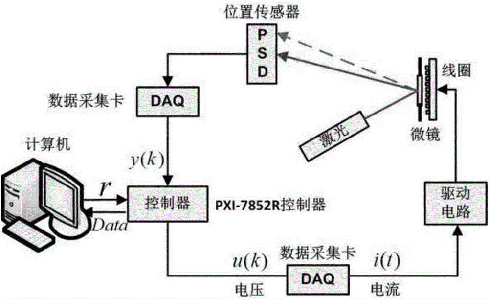
[0067] See Image 6 , Image 6 is the H of the electromagnetically driven micromirror disclosed in this embodiment ∞ Flow chart of the control method. The H of the electromagnetically driven micromirror disclosed in this embodiment ∞ The control method, on the basis of ensuring the good dynamic and static characteristics of the electromagnetic micromirror system, improves the dynamic robustness to unmodeled, reduces the power consumption of the controller, and suppresses the output noise.

[0068] Combine below Figure 1-Figure 6 , specifying an electromagnetically driven micromirror H ∞ The detailed procedure of the control method. as attached Image 6 As shown, the H of the electromagnetically driven micromirror ∞ The control method includes the following steps:

[0069] Step S1, selection of an optimization model.

[0070] h ∞ The standard control models mainly include: a mixed sensitivity model for comprehensive design, a sensitivity mini...

Example Embodiment

[0109] Embodiment two

[0110] This embodiment discloses an electromagnetically driven micromirror H ∞ control system, the H ∞ The control system includes:

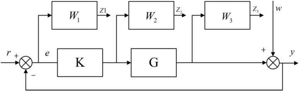
[0111] The optimization model selection module, which selects the optimized H according to the target performance requirements ∞ standard control model, the H ∞ Standard control models include: mixed sensitivity model for comprehensive design, sensitivity minimization model for suppressing interference, and mixed sensitivity model for comprehensive design of system perturbation robustness model. For the above modes, let G be the transfer function of the controlled object, and K be H ∞ controller transfer function, W 1 , W 2 , W 3 is the weight function, let the system open-loop transfer function be L, where L=KG; let S=1 / (I+GK) -1 ,R=K / (I+GK) -1 ,T=GK / (I+GK) -1 , where S is the sensitivity function, which is the transfer function from external disturbance e to output y, which represents the ability of the system ...


PUM


Abstract

The invention discloses an electromagnetically-driven micro mirror H-infinity control method and an H-infinity control system, which are applied to an electromagnetically driven micro mirror platform composed of an NI PXI controller and LabVIEW software and other hardware equipment. The control method comprises the following steps: S1, selecting an optimization model; S2, selecting a weighting function; S3, regulating the parameters of the weighting function; S4, solving an H-infinity controller; S5, analyzing the performance of a closed-loop system; and S6, discretizing the H-infinity controller through a Z transformation method. The electromagnetically-driven micro mirror H-infinity control method is disclosed in view of the shortcomings of the existing electromagnetically driven micro mirror PID control method. On the basis of ensuring good dynamic and static characteristics of the micro mirror system, the method improves the un-modeled dynamic robust performance of the system, reduces the power consumption of the controller, and restrains the output noise. The method achieves a good control effect, and is more in line with the requirements of practical application.

Description

technical field [0001] The present invention relates to the field of control technology of micro-electromechanical systems (MEMS), in particular to an electromagnetically driven micromirror H ∞ Control method and system. Background technique [0002] MEMS micromirrors are the most widely used devices in the field of micro-opto-electromechanical systems. Its structure generally includes mirrors, torsion bars, supporting devices, driving devices, etc., and its size is generally on the micron scale. It has the characteristics of miniaturization, high integration, low driving energy, good dynamic performance, and mass production of micro-opto-electromechanical systems. Widely used in optical communication, barcode recognition, projection imaging, medical equipment, consumer electronics and other fields. Common driving methods mainly include: electrothermal drive, piezoelectric drive, electrostatic drive, electromagnetic drive, etc. Among them, electromagnetically driven micr...

Claims


Application Information

Patent Timeline
IPC IPC(8): G05B13/04
Inventor 谢巍李冠霖张浪文
Owner SOUTH CHINA UNIV OF TECH
Why Eureka
Try Eureka