Embedded packaging structure based on semiconductor chip packaging body and packaging method thereof

A technology of chip packaging and packaging structure, which is applied in the direction of semiconductor devices, semiconductor/solid-state device manufacturing, semiconductor/solid-state device components, etc. It can solve the problems of insufficient welding precision, complex solder reflow process control, and hinder the development of miniaturization of semiconductor packaging devices, etc. problem, to achieve the effect of reducing the assembly area and greatly increasing the assembly area

Inactive Publication Date: 2017-05-10
蔡亲佳
View PDF4 Cites 7 Cited by
  • Summary
  • Abstract
  • Description
  • Claims
  • Application Information

AI Technical Summary

Problems solved by technology

[0004] At present, the solder connection of surface mount requires a large pitch between the pad and the pad of the semiconductor package device, such as the pad / pad pitch = 280 microns / 400 microns, the soldering is not precise enough, and the solder connection needs to be more complicated. Solder reflow process control;
[0005] In addition, the semiconductor packaging device is assembled on the circuit board by surface mount method. Due to the relatively large area of ​​the semiconductor packaging device, it will occupy a large surface area of ​​the circuit board, which hinders the miniaturization of semiconductor packaging device assembly.

Method used


Image

  • Embedded packaging structure based on semiconductor chip packaging body and packaging method thereof
  • Embedded packaging structure based on semiconductor chip packaging body and packaging method thereof
  • Embedded packaging structure based on semiconductor chip packaging body and packaging method thereof

Examples


Embodiment Construction

[0074] The preferred embodiments of the present invention will be described in detail below in conjunction with the accompanying drawings, so that the advantages and features of the present invention can be more easily understood by those skilled in the art, so as to define the protection scope of the present invention more clearly.

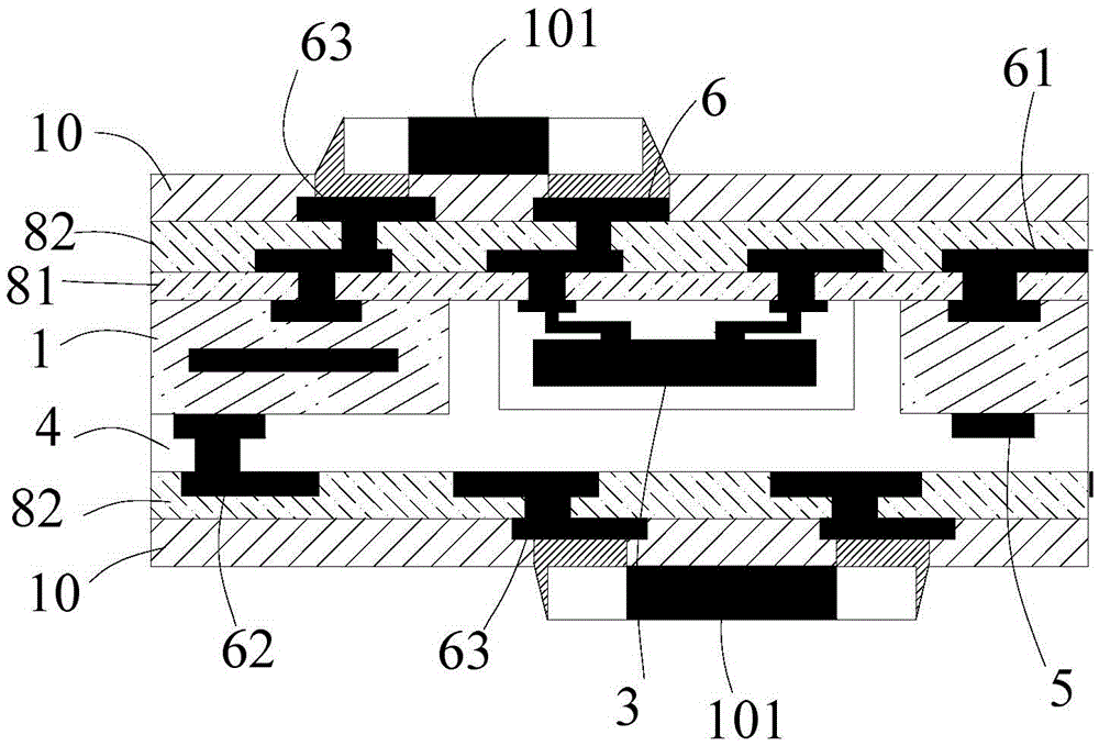
[0075] The embedded package structure based on semiconductor chip package in a specific embodiment of the present invention, refer to figure 1 As shown, the embedded package structure specifically includes:

[0076] A circuit board 1, that is, a circuit carrier for packaging a semiconductor chip package, which has a first surface 11 and a second surface 12 oppositely arranged;

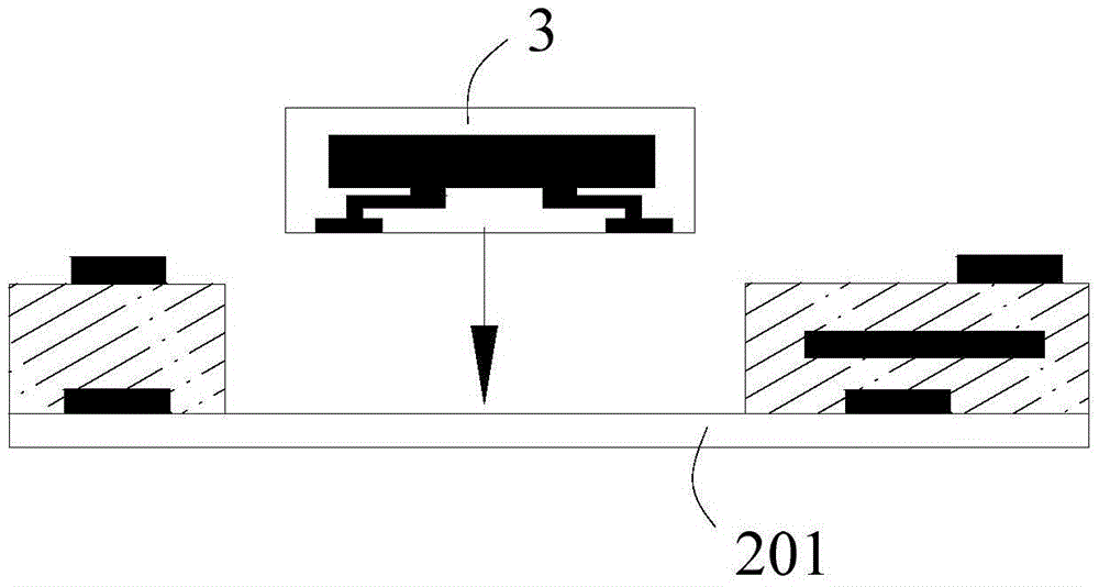
[0077] At least one opening or cavity 2 for accommodating a semiconductor chip package 3 provided in the circuit board 1;

[0078] a semiconductor chip package 3 disposed in the opening or cavity 2;

[0079] The packaging material 4 is at least used to cover the first s...


PUM


Abstract

The invention discloses an embedded packaging structure based on a semiconductor chip packaging body and a packaging method thereof. The embedded packaging structure comprises a circuit board having a first surface and a second surface which are oppositely arranged, at least one opening or chamber which is arranged in the circuit board and is used for accommodating the semiconductor chip packaging body, the semiconductor chip packaging body arranged in the opening or the chamber, a packaging material at least used for covering the first surface of the circuit board and filling space of the opening or the chamber not being occupied by the semiconductor chip packaging body, and a rewiring layer at least used for electrically connecting the semiconductor chip packaging body and the circuit board. The embedded packaging structure is advantaged in that the semiconductor chip packaging body is assembled through employing the circuit board embedding technology, an assembling technology process of the semiconductor chip packaging body can be simplified, assembling quality and performance can be improved, and an assembling area can be effectively reduced.

Description

technical field [0001] The invention relates to a high-end circuit carrier board packaging structure, in particular to an embedded packaging structure based on a semiconductor chip package and a packaging method thereof. Background technique [0002] Surface mount technology (Surface Mount Technology, SMT) is a method of mounting non-pin or short-lead surface mount components (SMC / SMD for short, Chinese chip components) on printed circuit boards (Printed Circuit Board, PCB) The circuit assembly technology that solders and assembles the surface of the substrate or the surface of other substrates by reflow soldering or dip soldering. Surface mount technology has high assembly density, small size and light weight of electronic products. The volume and weight of SMD components are only about 1 / 10 of traditional plug-in components. Generally, after SMT is used, the volume of electronic products is reduced by 40% to 60%. The weight is reduced by 60% to 80%. The assembly of semic...

Claims


Application Information

Patent Timeline
Patent Type & Authority Applications(China)
IPC IPC(8): H01L23/535H01L23/485H01L23/498H01L21/60
CPCH01L23/485H01L23/49827H01L23/535H01L24/81H01L2224/81H01L21/568H01L2224/04105H01L2224/19H01L2224/96H01L2924/19105
Inventor 蔡亲佳
Owner 蔡亲佳
Why Eureka
Try Eureka