
A kind of lug and pole piece transfer structure, battery and manufacturing method thereof

A pole ear and switching technology, applied in the direction of structural parts, circuits, electrical components, etc., can solve the problems of rapid mass production and scale difficulties, difficult soldering of tin, and inability to use, achieve good safety protection performance, reduce explosions and the incidence of combustion, the effect of improving energy density

Active Publication Date: 2019-12-10
SPRINGPOWER TECHNOLOGY (SHENZHEN) CO LTD
View PDF1 Cites 0 Cited by
  • Summary
  • Abstract
  • Description
  • Claims
  • Application Information

AI Technical Summary

Problems solved by technology

[0004] At present, tabs are produced on a large scale in the industry, and the thinner tabs are 0.10mm and 0.08mm. However, the thinner the tabs, the more difficult it is to quickly mass-produce and scale them up. Tin is difficult to achieve good soldering
[0005] On the other hand, with the improvement of energy density, the safety performance of the battery will further deteriorate. An existing solution is to install a safety vest structure on the battery, as shown in the patent "CN201620099936.9", by setting an additional The blank area of ​​the pole piece is wound to form a vest area to improve the safety of puncture and avoid safety problems such as burning or explosion. However, the safety vest structure includes at least one layer of aluminum foil thickness, which has a certain impact on the energy density of the battery. , in a high-voltage system with higher energy density, such as LCO 4.40V, the energy density must reach more than 720Wh / L, so the battery core designer cannot use the traditional safety vest structure

Method used


Image

  • A kind of lug and pole piece transfer structure, battery and manufacturing method thereof
  • A kind of lug and pole piece transfer structure, battery and manufacturing method thereof
  • A kind of lug and pole piece transfer structure, battery and manufacturing method thereof

Examples


Embodiment 1

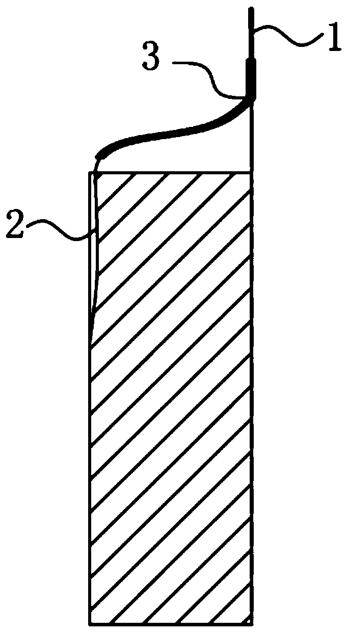
[0033] see figure 1 As shown, this embodiment discloses a tab pole piece transfer structure, including a metal tab 1, a metal strip 2 and an electrode piece, the electrode piece has an electrode collector, and one end of the metal strip 2 is attached to the The other end of the electrode collector surface is connected to the metal tab 1, the thickness of the metal strip 2 is 10-59 μm, the thickness of the metal tab 1 is greater than 50 μm, and the thickness of the metal tab 1 is greater than the thickness of the metal strip 2.

[0034] In this transfer structure, by setting the metal strip 2 with a thickness of only 10-59 μm in direct contact with the electrode collector of the electrode sheet, and then transferring the metal strip 2 through the metal tab 1 of ordinary thickness, it can be as far as possible Avoiding the influence of the thickness of the tab on the overall thickness of the battery, the section thickness of the battery cell using this tab pole piece transfer s...

Embodiment 2

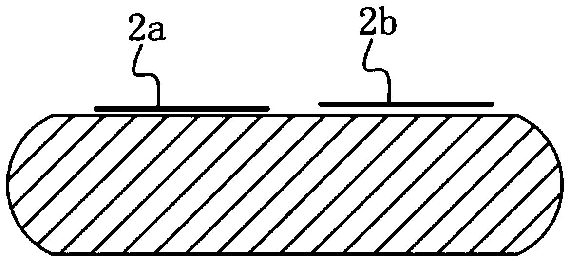
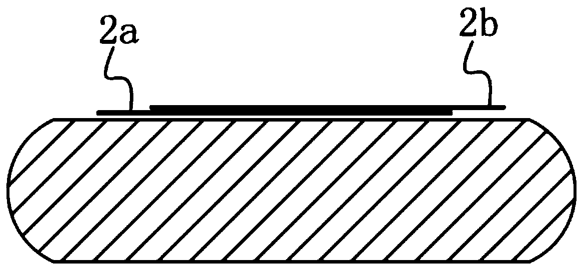
[0048] In another embodiment of the present invention, a battery cell is disclosed, including a diaphragm and the tab pole piece transfer structure as described in Embodiment 1, the number of the tab pole piece transition structures is 2, They are respectively the tab transfer structure of the positive electrode and the tab transfer structure of the negative electrode. The electrode sheet includes a positive electrode sheet and a negative electrode sheet. The positive electrode sheet includes a positive electrode collector and is coated on the positive electrode collector The positive electrode active material on the negative electrode sheet includes a negative electrode current collector and a negative electrode active material coated on the negative electrode current collector. The metal belt 2 includes a positive electrode metal belt 2a and a negative electrode metal belt 2b. The metal tab 1 includes a positive electrode tab and a negative electrode tab. The positive electro...

Embodiment 3

[0057] This embodiment discloses a battery manufacturing method as described in Embodiment 2, which is characterized in that it includes the following steps:

[0058] Ultrasonic welding is performed on the positive electrode metal strip 2a and the positive electrode tab, and ultrasonic welding is performed on the negative electrode metal strip 2b and the negative electrode tab, and the welding points are respectively wrapped with insulating tape 3;

[0059] To obtain a positive electrode sheet and a negative electrode sheet, the end of the positive electrode metal strip 2a away from the positive electrode lug is ultrasonically welded on the positive electrode current collector at the end of the positive electrode sheet, and the positive electrode metal strip 2a is along the length direction of the positive electrode sheet The vertical direction is drawn; the negative electrode metal strip 2b is ultrasonically welded on the negative electrode current collector at the end of the ...


PUM

PropertyMeasurementUnit
thicknessaaaaaaaaaa
thicknessaaaaaaaaaa
thicknessaaaaaaaaaa

Abstract

In order to overcome the problems of energy density improvement and battery safety performance that are difficult to solve in the existing battery structure, the present invention provides a tab pole piece transfer structure, including metal tabs, metal strips and electrode pieces, the electrode piece There is an electrode collector, one end of the metal strip is attached to the surface of the electrode collector, and the other end is connected to the metal tab, the thickness of the metal strip is 10-59 μm, and the thickness of the metal tab is greater than 50 μm, and the thickness of the metal tab is greater than that of the metal strip. At the same time, the invention also discloses an electric core and a manufacturing method thereof. The tab pole piece transfer structure and the battery cell provided by the present invention can effectively reduce the thickness of the battery to increase its energy density, and at the same time have better safety performance.

Description

technical field [0001] The invention belongs to the technical field of battery structures, and in particular relates to a lug and pole piece transfer structure, a battery cell and a manufacturing method thereof. Background technique [0002] At present, in the manufacturing process of lithium-ion batteries, the improvement of the energy density of the battery cell is particularly important for the performance evaluation of the battery, especially for consumer mobile phone batteries. The thickness of the fluid, the thickness of the tabs, and the thickness of the packaging aluminum-plastic film are used to increase the thickness space, thereby increasing the energy density. [0003] Among them, by increasing the positive and negative electrode voltage matching platform and material compaction, reducing the thickness of the positive and negative electrode current collectors, and reducing the thickness of the aluminum-plastic film, a long development and verification cycle is re...

Claims


Application Information

Patent Timeline
Patent Type & Authority Patents(China)
IPC IPC(8): H01M2/26H01M10/0587
CPCH01M10/0587H01M50/538Y02E60/10Y02P70/50
Inventor 王立福李伟于立娟周燕
Owner SPRINGPOWER TECHNOLOGY (SHENZHEN) CO LTD
Learn More