Electrical isolator packaging structure and manufacturing method for electrical isolator

A manufacturing method and technology of an electrical isolator, which is applied in the field of signal transmission, can solve problems such as the incompatibility of light-emitting diode processes, and achieve the effects of reducing signal distortion and power consumption

Inactive Publication Date: 2017-05-10
IND TECH RES INST
View PDF3 Cites 0 Cited by
  • Summary
  • Abstract
  • Description
  • Claims
  • Application Information

AI Technical Summary

Problems solved by technology

If an optocoupler is used as an electrical isolator, since the process of light-emitting diodes (LEDs) is not compatible with the transistor process (for example, CMOS process), and the LED itself has issues such as light decay, heat loss, etc., it is impossible to integrate LEDs into In-chip but need additional packaging
If a transformer or capacitor that can be integrated into the chip is used as an electrical isolator, it may be necessary to transmit high-frequency signals to achieve effective transmission efficiency, resulting in the need to design additional modulation and demodulation functions for circuits using this type of electrical isolator , in order to successfully transmit the signal

Method used


Image

  • Electrical isolator packaging structure and manufacturing method for electrical isolator
  • Electrical isolator packaging structure and manufacturing method for electrical isolator
  • Electrical isolator packaging structure and manufacturing method for electrical isolator

Examples


Embodiment Construction

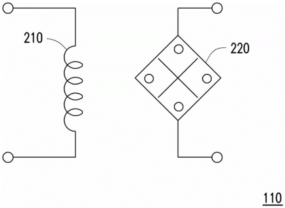
[0043] figure 1 is a schematic diagram of a circuit 100 using an electrical isolator 110 according to an embodiment of the present invention. The circuit 100 includes a galvanic isolator 110 , a first circuit 120 , a second circuit 130 and a load 140 . The power supply of the first circuit 120 is connected to the first voltage domain VD1, and the power supply of the second circuit 130 is connected to the second voltage domain VD2. The first circuit 120 may be an input stage circuit or a control circuit, and the second circuit 130 may be an output stage circuit. The load 140 is connected to the output terminal of the second circuit 130 .

[0044] In this embodiment, the first voltage domain VD1 and the second voltage domain VD2 may be different. The circuit 100 is applicable to a power circuit system, so the second voltage domain VD2 may range from 20V to 35kV, depending on the applied power circuit system. The first voltage domain VD1 is a commonly used voltage range for c...


PUM


Abstract

An electrical isolator packaging structure and a manufacturing method of an electrical isolator are provided. The electrical isolator packaging structure includes a first substrate, a second substrate, a coil, and a magnetic field (MF) sensor. The coil is disposed on the first substrate. The MF sensor is disposed on the second substrate. The position of the coil is arranged according to the position of the MF sensor such that the coil transmits a signal to the MF sensor. Thus, the electrical isolator can be implemented by magnetic coupling with the coil and the MF sensor.

Description

technical field [0001] The invention relates to a signal transmission technology, and in particular to an electrical isolator assembly structure and a manufacturing method of the electrical isolator. Background technique [0002] In the field of signal transmission, it is often necessary to transfer signals or energy from circuits in one voltage domain to circuits in another voltage domain, or to transfer signals or energy from one medium to another. However, due to the difference in voltage domain or medium type, the signal may interfere or break down the surrounding circuits through the parasitic path during the transmission process, resulting in damage. Therefore, for the sake of circuit reliability, electrical isolators, couplers or isolation barriers are usually used to transmit signals between circuits in different voltage domains to protect the circuits. [0003] Galvanic isolators can be used in many power circuit fields, such as power systems (such as power supplie...

Claims


Application Information

Patent Timeline
Patent Type & Authority Applications(China)
IPC IPC(8): H03K19/0175
CPCH03K19/017545H01L2224/04042H01L2224/32145H01L2224/48137H01L2224/73265H01F27/2804H01F2027/2809H01L23/5227H01L28/10H10B61/00H10N59/00H10N52/80H01F41/041
Inventor 张元泰庄凯翔
Owner IND TECH RES INST
Why Eureka
Try Eureka